A6.5 list of the arithmetic block parameters, A6.5, A6-7 – Yokogawa digitalYEWFLO (DY-FF) User Manual
Page 114
A6-7
IM 01F06F00-01EN
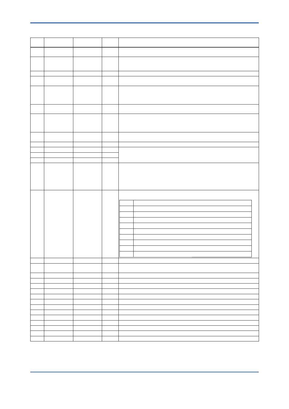
A6.5 List of the Arithmetic Block Parameters
Relative
Index
Parameter
Write Mode
Initial
Value
Description / Remarks
0
Block Header
Block Tag = O/S TAG=“AR”
Information relating to this function block, such as block tag, DD revision, and
execution time
1 ST_REV
—
0
Indicates the revision level of the set parameters associated with the Arithmetic
block. If a setting is modifi ed, this revision is updated. It is used to check for
parameter changes, etc.
2
TAG_DESC
AUTO
Null
A universal parameter that stores comments describing tag information
3 STRATEGY
AUTO
1
A universal parameter intended for use by a high-level system to identify function
blocks
4 ALERT_KEY
AUTO
1
Key information used to identify the location at which an alert has occurred.
Generally, this parameter is used by a high-level system to identify specifi c areas in
a plant that are under the control of specifi c operators, to separate necessary alerts
only. This is one of the universal parameters.
5 MODE_BLK
AUTO
A universal parameter representing the operation status of the Arithmetic block. It
consists of the Actual, Target, Permit, and Normal modes.
6 BLOCK_ERR
—
0
Indicates the error status relating to the Arithmetic block.
The bit used by this function block is as follows:
Bit 1: Block Confi guration Error
Bit 15: O/S mode
7 PV
—
0
The result of a range extension function is substituted into this.
When viewed from the computing equation, PV is the main input.
8 OUT
MAN
0 Block
output
9 PRE_OUT
—
0 Always indicates the calculation result. The value is substituted into OUT in Auto
mode. Indicates PV scaling (for making a memo).
Output scaling for the host (for making a memo)
10 PV_SCALE
O/S
11 OUT_RANGE
AUTO
12 GRANT_DENY
AUTO
0
The parameter used to check if various operations have been executed. The bits
in the GRANT parameter corresponding to various operations are set before any
of them are executed. After the operations are complete, the DENY parameter
is checked to fi nd out if any bit corresponding to the relevant operation has been
set. If no bit has been set, it is evident that the operations have been executed
successfully.
13 INPUT_OPTS
AUTO
0
Determines whether an input is used as a “good” input when the input status is
"bad" or “uncertain.”
Bit
Function
0
Handles IN as “good” input if its status is “uncertain.”
1
Handles IN_LO as “good” input if its status is “uncertain.”
2
Handles IN_1 as “good” input if its status is “uncertain.”
3
Handles IN_1 as “good” input if its status is “bad.”
4
Handles IN_2 as “good” input if its status is “uncertain.”
5
Handles IN_2 as “good” input if its status is “bad.”
6
Handles IN_3 as “good” input if its status is “uncertain.”
7
Handles IN_3 as “good” input if its status is “bad.”
8 to 15 Reserved
14 IN
AUTO
0 Input
block
15 IN_LO
AUTO
0
Input for a low-range transmitter.
This is used for the range extension function.
16
IN_1
AUTO
0
Auxiliary input 1
17
IN_2
AUTO
0
Auxiliary input 2
18
IN_3
AUTO
0
Auxiliary input 3
19
RANGE_HI
AUTO
0
High limit for switching to a high-range transmitter by the range extension function.
20
RANGE_LO
AUTO
0
Low limit for switching to a low-range transmitter by the range extension function.
21 BIAS_IN_1
AUTO
0 IN_1
bias
22 GAIN_IN_1
AUTO
0 IN_1
gain
23 BIAS_IN_2
AUTO
0 IN_2
bias
24 GAIN_IN_2
AUTO
0 IN_2
gain
25 BIAS_IN_3
AUTO
0 IN_3
bias
26 GAIN_IN_3
AUTO
0 IN_3
gain
27
COMP_HI_LIM
AUTO
+INF High limit of compensation factor f
28
COMP_LO_LIM
AUTO
-INF Low limit of compensation factor f