A7.5.2 descriptions for lm parameters, A7.5.2, A7-6 – Yokogawa digitalYEWFLO (DY-FF) User Manual
Page 123
A7-6
IM 01F06F00-01EN
A7.5.2 Descriptions for LM Parameters
The following describes LM parameters of
digitalYEWFLO.
NOTE: Do not turn off the power to the digitalYEWFLO for 60
seconds after making a change to its parameter settings.
(1) DlmeLinkMasterCapabilitiesVariable
Bit
Position
Meaning Description Value
B3: 0x04
LAS
Schedule in
Non-volatile
Memory
Whether the LAS schedule can
(= 1) or cannot (= 0) be saved to
the non-volatile memory
1
B2: 0x02
Last Values
Record
Supported
Whether to support (= 1) or not to
support (= 0) LastValuesRecord.
0
B1: 0x01
Link Master
Statistics
Record
Supported
Whether to support (= 1) or not
to support (= 0)
DlmeLinkMasterStatisticsRecord.
0
(2) DlmeLinkMasterInfoRecord
Sub-
index
Element
Size
[bytes]
Descrip-
tion
1 MaxSchedulingOverhead
1 V(MSO)
2 DefMinTokenDelegTime
2 V(DMDT)
3 DefTokenHoldTime
2 V(DTHT)
4 TargetTokenRotTime
2 V(TTRT)
5 LinkMaintTokHoldTime
2 V(LTHT)
6 TimeDistributionPeriod
4 V(TDP)
7 MaximumInactivityToClaimLasDelay
2 V(MICD)
8 LasDatabaseStatusSpduDistributionPeriod 2 V(LDDP)
(3) PrimaryLinkMasterFlagVariable
Explicitly declares the LAS. Writing “true” (0xFF)
to this parameter in a device causes that device to
attempt to become the LAS. However, a request
of writing “true” to this parameter in a device is
rejected if the value of the same parameter in any
other device that has a smaller node address within
the same segment is true.
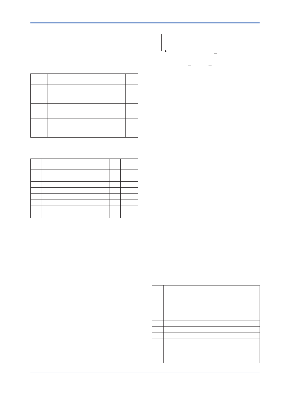
(4) LiveListStatusArrayVariable
A 32-byte variable, in which each bit represents the
status of whether a device on the same segment
is live or not. The leading bit corresponds to the
device address 0x00, and fi nal bit to 0xFF. The
value of LiveListStatusArrayVariable in the case
where devices having the addresses 0x10 and
0x15 in the fi eldbus segment is shown below.
0x00 00 84 00 00 00 00 00 00 00 00 00 00 00
00 00 00 00 00 00 00 00 00 00
00 00 00 00 00 00 00 00
Bit correspondences: 0 0 0 0 0 0 0 0 0 0 0
0u00
0 0 0 0 0 1 0 0 0 0 1 0 0...
0u10 0u15
FA0704.ai
(5) MaxTokenHoldTimeArray
An 8 × 64-byte variable, in which each set of 2 bytes
represents the delegation time (set as an octet time)
assigned to a device. The delegation time denotes
a time period that is given to a device by means of
a PT message sent from the LAS within each token
circulation cycle.
The leading 2 bytes correspond to the device
address 0x00, and the fi nal 2 bytes to the device
address 0xFF. Specify the subindex to access this
parameter.
(6) BootOperatFunctionalClass
Writing 1 to this parameter in a device and
restarting the device causes the device to start as
a basic device. On the contrary, writing 2 to this
parameter and restarting the device causes the
device to start as an LM.
(7) CurrentLinkSettingRecord
and
Confi guredLinkSettingsRecord
CurrentLinkSettingRecord indicates the
bus parameter settings currently used.
Confi guredLinkSettingsRecord indicates the
bus parameter settings to be used when the
device becomes the LAS. Thus, when a device
is the LAS, its CurrentLinkSettingRecord and
Confi guredLinkSettingsRecord have the same
values.
Sub-
index
Element
Size
[bytes]
Descrip-
tion
1 SlotTime
2 V(ST)
2 PerDlpduPhlOverhead
1 V(PhLO)
3 MaxResponseDelay
1 V(MRD)
4 FirstUnpolledNodeId
1 V(FUN)
5 ThisLink
2 V(TL)
6 MinInterPduDelay
1 V(MID)
7 NumConsecUnpolledNodeId
1 V(NUN)
8 PreambleExtension
1 V(PhPE)
9 PostTransGapExtension
1 V(PhGE)
10 MaxInterChanSignalSkew
1 V(PhIS)
11 TimeSyncClass
1 V(TSC)