Warning, Maintenance and repair – Yokogawa digitalYEWFLO (DY-FF) User Manual
Page 52
<10. EXPLOSION PROTECTED TYPE INSTRUMENT>
10-3
IM 01F06F00-01EN
Maintenance and Repair
WARNING
• The instrument modifi cation or parts
replacement by other than authorized
representative of Yokogawa Electric
Corporation is prohibited and will void the
certifi cation.
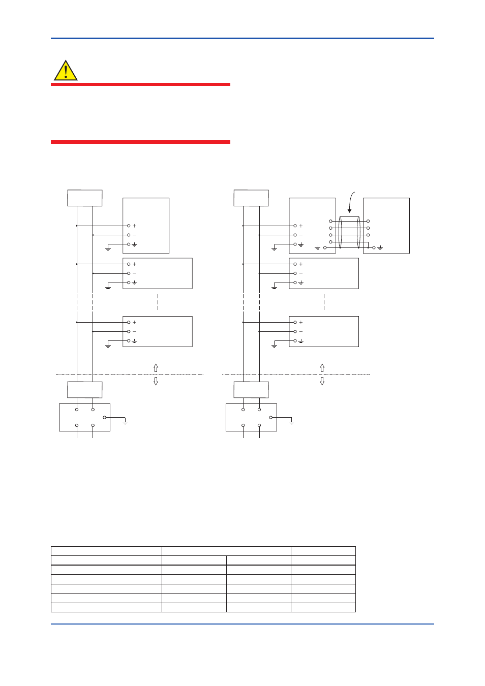
Installation Diagram of Intrinsically safe (and Note)
F1002.ai
DY
(Flowmeter)
Terminator
Terminator
Safety Barriar
Field Instrument
Field Instrument
Hazardous Location
Non Hazardous Location
DYA
(Converter)
DY-N
(Flowmeter)
Terminator
Terminator
Safety Barriar
Field Instrument
Field Instrument
Hazardous Location
Non Hazardous Location
A
B
T(*1)
A
B
T
C
DYC (Signal Cable)
[ Integral type ]
[ Remote type ]
(*1): Wire for T termanal
With temperature sensor type: Installed
Without temperature sensor type: Not Installed
Note
In the rating 1, the output current of the barrier must be limited by a resistor ‘Ra’ such that Io=Uo/Ra.
In the rating 2, the output of the barrier must be the characteristics of the trapezoid or the rectangle and this transmitter can be
connected to Fieldbus equipment which are in according to the FISCO model.
The terminators may be built-in by a barrier.
More than one field instrument may be connected to the power supply line.
The terminator and the safety barrier shall be certified.
Electrical data
II C
II B
Rating1 (Entity)
Rating2 (FISCO)
Rating3 (FISCO)
Maximum Input Voltage Ui
24V
17.5V
17.5V
Maximum Input Current Ii
250mA
380mA
460mA
Maximum Input Power Pi
1.2W
5.32W
5.32W
Maximum Internal Capacitance Ci
1.76nF
1.76nF
1.76nF
Maximum Internal Inductance Li
0
0
0