A5.7 list of integrator block parameters, A5.7, A5-10 – Yokogawa digitalYEWFLO (DY-FF) User Manual
Page 106
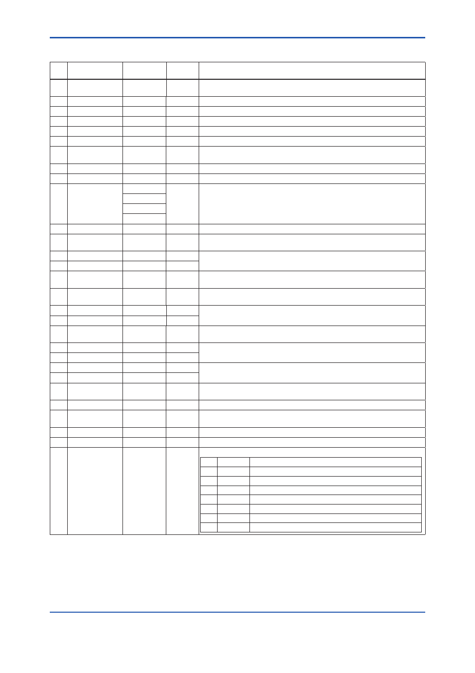
A5.7 List of Integrator Block Parameters
Index Parameter Name Initial Value
Write
Mode
Defi nition
0 BLOCK_HEADER TAG:
“IT”
Block Tag
=O/S
Information relating to this function block, such as block tag,
DD revision, execution time
1 ST_REV
0
—
The revision level of the set parameters associated with the Integrator block
2 TAG_DESC
Spaces
AUTO
Stores comments describing tag information.
3 STRATEGY
1
AUTO
The
strategy
fi eld is used by a high-level system to identify the function block.
4 ALERT_KEY
1
AUTO
Key information used to identify the location at which an alert occurred
5 MODE_BLK
AUTO
Integrator block mode. O/S, MAN, and AUTO are supported.
6 BLOCK_ERR
0
—
Indicates the active error conditions associated with the function block in bit
strings.
7 TOTAL_SP
1000000.0
AUTO
The setpoint of an integrated value or a start value for counting down
8 OUT
MAN
The block output
9 OUT_RANGE
100000
Set scaling for output display. This does not affect operation of the function block.
It is used for making memos.
0.0
m3(1034)
0
10 GRANT_DENY
0
The parameter for checking if various operations have been executed
11 STATUS_OPTS
0
O/S
Allows you to select a status-related option.
The Integrator block uses “Uncertain if Man mode” only.
12 IN_1
0.0
AUTO
Inputs fl ow (Rate, Accum) signals from the AI block or PI block.
13 IN_2
0.0
AUTO
14 OUT_TRIP
0
Value:
AUTO
An output parameter informing the user that the integrated value has exceeded
the setpoint
15 OUT_PTRIP
0
Value:
AUTO
An output parameter informing the user that the integrated value is reaching the
setpoint
16 TIME_UNIT1
sec(1)
MAN
Set the time unit of the Rate (kg/s, kg/min, kg/h ... etc.) of the corresponding IN.
17 TIME_UNIT2
sec(1)
MAN
18 UNIT_CONV
1.0
AUTO
Specify the unit conversion factor for standardizing the unit of IN_2 into that of
IN_1.
19 PULSE_VAL1
1.0
MAN Set the factor for converting the number of pulses for the corresponding IN into an
appropriate engineering unit.
20 PULSE_VAL2
1.0
MAN
21 REV_FLOW1
0
AUTO Selector switch used to specify the fl uid fl ow direction (forward/reverse) with
respect to the corresponding IN
22 REV_FLOW2
0
AUTO
23 RESET_IN
0
AUTO
The parameter that receives a reset request from an external block to reset the
integrated values
24 STOTAL
0.0
—
Indicates the snapshot of OUT just before a reset.
25 RTOTAL
0.0
MAN
Indicates the integrated value of the absolute values of the increments if the input
status is “Bad.”
26 SRTOTAL
0.0
—
Indicates the snapshot of RTOTAL just before a reset.
27 SSP
0.0
—
Indicates the snapshot of TOTAL_SP just before a reset.
28 INTEG_TYPE
UP_AUTO
(1) AUTO
Integration Type Setting
Value Name
Description
1
UP_AUTO
Counts up and is automatically reset when TOTAL_SP is reached.
2
UP_DEM
Counts up and is reset as demanded.
3
DN_AUTO
Counts down and is automatically reset when “0” is reached.
4
DN_DEM
Counts down and is reset as demanded.
5
PERIODIC Counts up and is reset at periods specifi ed in CLOCK_PER.
6
DEMAND
Counts up and is reset as demanded.
7
PER&DEM Counts up and is reset periodically or as demanded.
A5-10
IM 01F06F00-01EN