Warning, Special conditions for safe use, Installation – Yokogawa digitalYEWFLO (DY-FF) User Manual
Page 51: Operation
<10. EXPLOSION PROTECTED TYPE INSTRUMENT>
10-2
IM 01F06F00-01EN
(Integral Type Vortex Flowmeter)
Temperature Class
Ambient
Temperature
Process
Temperature
T4
60°C
≤135°C
T3
60°C
≤200°C
T2*
60°C
≤300°C
T1*
60°C
≤450°C
*: Use /HT version above 250°C
(Remote Type Vortex Flow Detector)
Temperature Class
Ambient
Temperature
Process
Temperature
T4
80°C
≤135°C
T3
80°C
≤200°C
T2*
80°C
≤300°C
T1*
80°C
≤450°C
*: Use /HT version above 250°C
Electrical data:
Supply and Output Circuit (SUPPLY + and -,
PULSE + and -);
Maximum Input Voltage Ui = 30 V
Maximum Input Current Ii = 165 mA
Maximum Input Power Pi = 0.9 W
Internal Capacitance Ci = 1.76nF
Internal Inductance Li = 0mH
For the connection of DYA to DY-N :
Maximum cable capacitance: 160nF
Electrical Connection: ANSI 1/2 NPT female, ISO
M20 X 1.5 female
Special conditions for safe use
1. For process temperatures above 250°C the fl ow
meters of the /HT version must be used.
2. Because the enclosures of the fl ow meters
and the fl ow converter are made of aluminium
alloy, when used in an potentially explosive
atmosphere requiring apparatus of equipment
categoly 1 G, they must be installed so, that even
in the event of rare incidents, an ignition source
due to impact of friction between the enclosure
and iron/steel is excluded.
Installation
WARNING
• All wiring shall comply with local installation
requirements and local electrical code.
• Use the suitable heat-resisting cables (over
90°C) for the digitalYEWFLO Model DY
Series Vortex Flowmeter when the ambient
temperature exceeds 60°C and/or the
process temperature exceeds 200°C.
• Cable glands, adapters and/or blanking
elements shall be of Ex “d” for Ex “d”
installations. They shall be installed so as to
maintain the specifi ed degree of protection
(IP Code) of the fl owmeter.
• Unused apertures shall be closed with
above-mentioned blanking elements (in case
of Ex “d” installations).
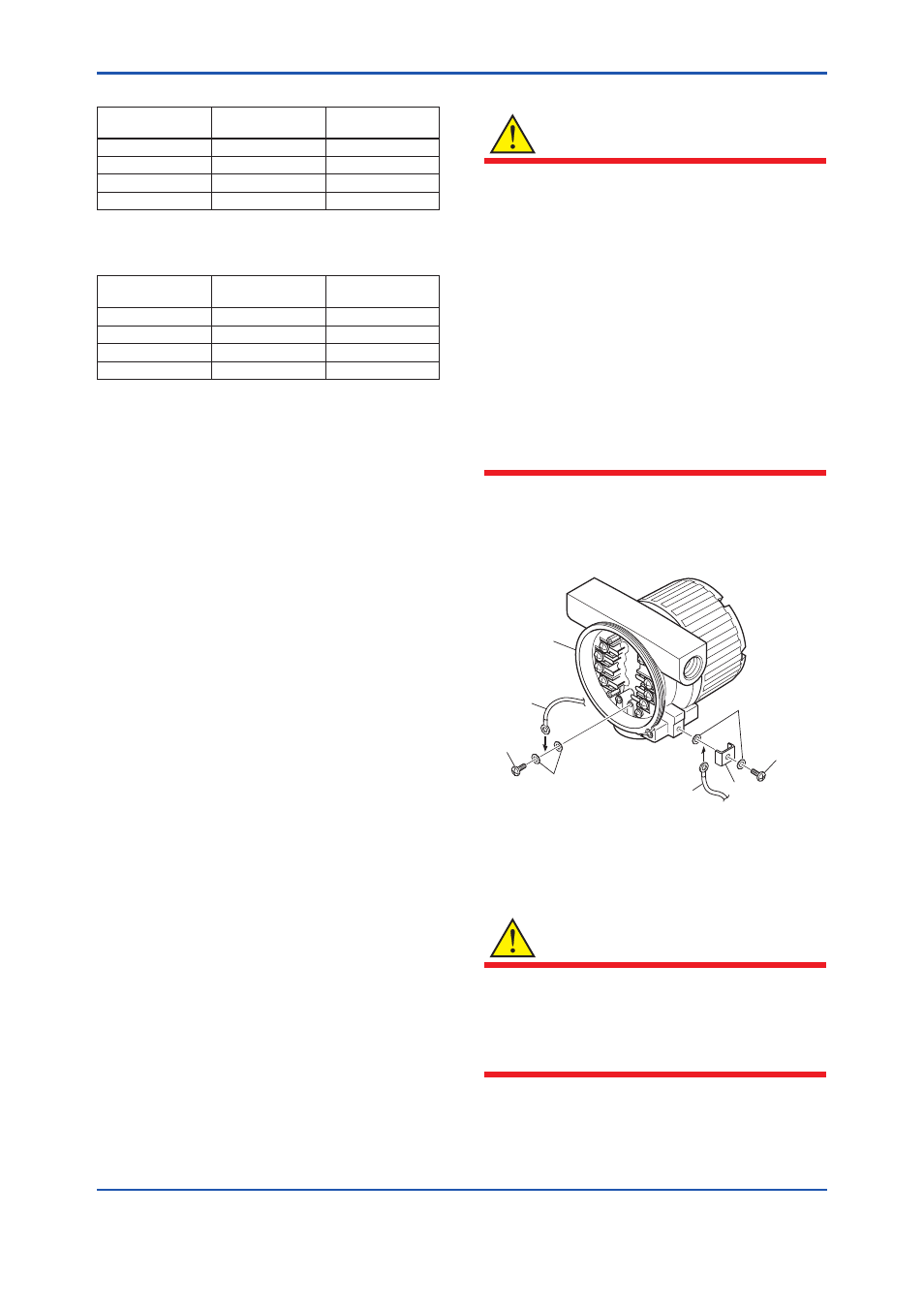
The grounding terminals are located on the inside
and outside of the terminal area.
Connect the cable to grounding terminal in
accordance with wiring procedure (1) or (2).
Case
Cable
Screw
(1) Internal grounding terminal
(2) External grounding terminal
Washer
Washer
Cable
Clamp
Screw
F1001.ai
Figure 10.1 Wiring Procedure for Grounding
Terminals for Flameproof
Operation
WARNING
• Wait 3 min. after power is turned off, before
opening the covers.
• Take care not to generate mechanical
spark when access to the instrument and
peripheral devices in hazardous locations.