Reference, Differential mode and common mode, Differential mode range and common mode range – Teledyne LeCroy DA1855A User Manual
Page 86: Common mode rejection ratio
DA1855A Differential Amplifier
80
922258-00 Rev A
Reference
Differential Mode and Common Mode
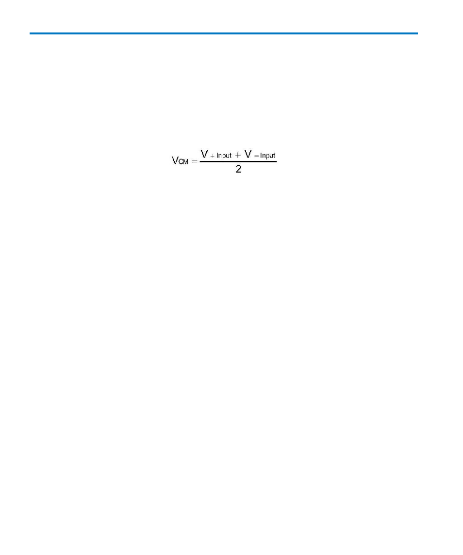
Differential amplifiers amplify the voltage difference which appears between the + input and –
input. This voltage is referred to as the Differential Mode or Normal Mode voltage. The voltage
component which is referenced to earth and is identical on both inputs is rejected by the amplifier.
This voltage is referred to as the Common Mode voltage and can be expressed as:
Differential Mode Range and Common Mode Range
Differential Mode range is the maximum signal which can be applied between the + and – inputs
without overloading the amplifier, which otherwise would result in clipping or distorting the
waveform measured by the oscilloscope.
The Common Mode Range is the maximum voltage with respect to earth ground which can be
applied to either input. Exceeding the common mode range can result in unpredictable
measurements. Because the Common Mode signal is normally rejected and not displayed on the
oscilloscope, you must be careful to avoid accidentally exceeding the common mode range.
Common Mode Rejection Ratio
The ideal differential amplifier would amplify only the differential mode voltage component and
reject all of the common mode voltage component. Real differential amplifiers are not perfect and a
small portion of the common mode voltage component appears at the output. Common Mode
Rejection Ratio (CMRR) is the measure of how much the amplifier rejects the common mode voltage
component. CMRR is equal to the differential mode gain (or normal gain) divided by the common
mode gain. Common mode gain is equal to the output voltage divided by the input voltage when
both inputs are driven by only the common mode signal. CMRR can be expressed as a ratio (e.g.
10000:1) or implicitly in dB (e.g. 80 dB). Higher numbers indicate greater rejection (better
performance).
The first order term which determines the CMRR is the relative gain matching between the + and –
input paths. To obtain high CMRR values, the input attenuators in a differential amplifier are
precisely matched to each other. The matching includes the DC attenuation as well as the
capacitance which determines the AC attenuation. As the frequency of the common mode
component increases, the effects of stray parasitic capacitance and inductance in determining the
AC component becomes more pronounced. The CMRR becomes smaller as the frequency increases.
Hence the CMRR is usually specified in a graph of CMRR versus common mode frequency.