Teledyne LeCroy DA1855A User Manual
Page 76
DA1855A Differential Amplifier
70
922258-00 Rev A
b. Set the DA1855A GAIN to X1, ATTENUATOR to ÷1.
c. Set the leveled sine wave generator output frequency to 50 kHz. If necessary adjust
the output amplitude for a display of exactly 6 divisions (300 mV) peak to peak.
d. Change the output frequency to 10 MHz, taking care not to change the output
amplitude.
e. Measure the peak to peak output amplitude of the DA1855A. Record the reading to
two digit resolution (xx0 mV) as ‘Amplifier Output Voltage at 10 MHz’ in the Test
Record.
f. Divide the measured output amplitude by 300 mV. Record the answer to two digit
resolution (0.xx) in the Test record. This is the ‘Differential Mode Gain at 10 MHz’.
g. Remove the leveled sine wave generator from the +INPUT of the DA1855A.
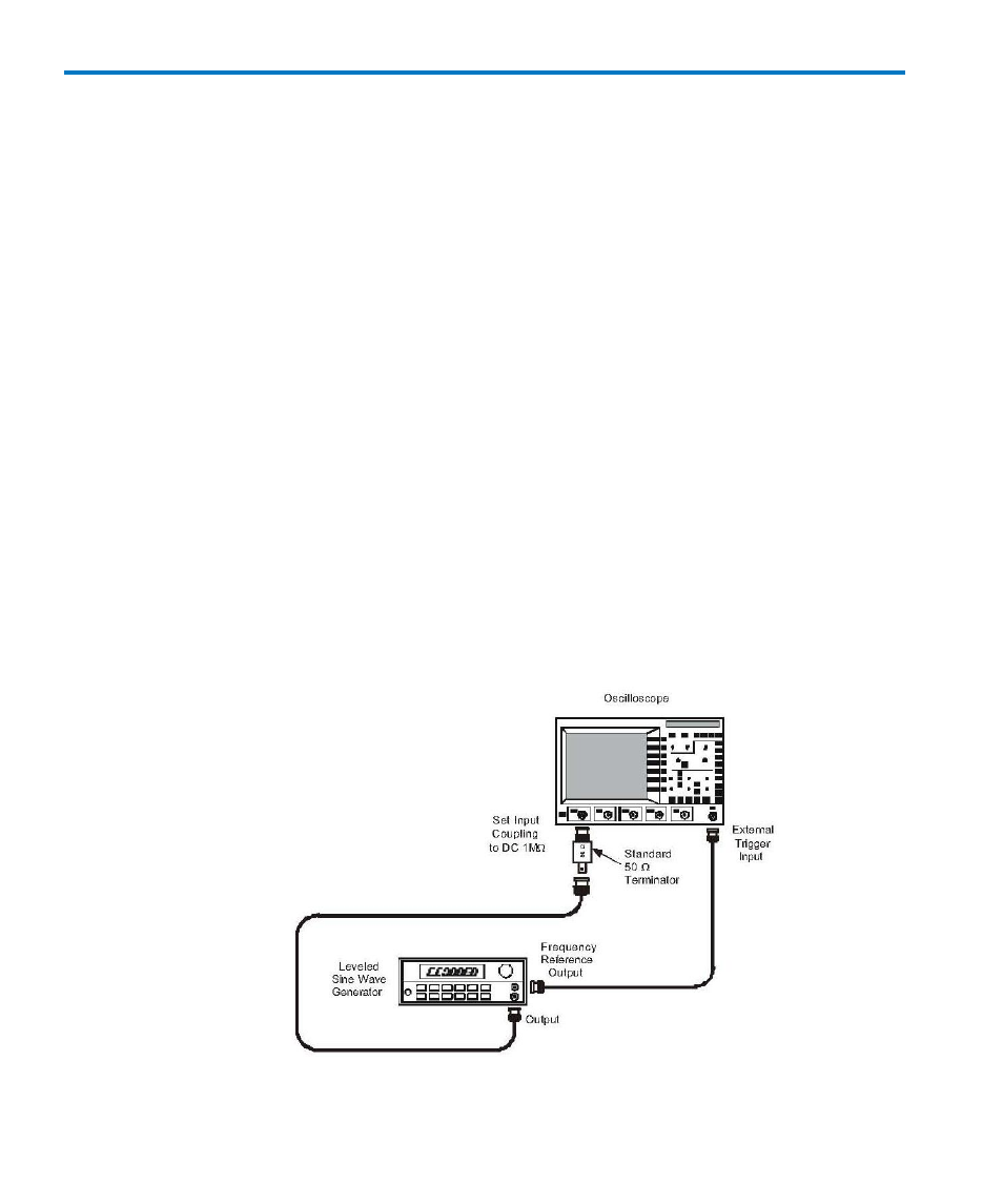
h. Connect a BNC cable from the Frequency Reference Signal Output of the sine wave
generator to the External Trigger Input of the oscilloscope. (If the sine wave
generator does not have a Frequency Reference Signal Output, insert a BNC Tee
adapter into the Output connector and attach the External Trigger BNC cable to the
BNC Tee.)
i. Disconnect the AMPLIFIER OUTPUT cable from the oscilloscope’s channel 1 and
connect the terminated end of the sine wave generator output cable to the channel
1 input of the oscilloscope. Refer to Figure 18.
Figure 18, HF CMRR Check Setup