Teledyne LeCroy DA1855A User Manual
Page 74
DA1855A Differential Amplifier
68
922258-00 Rev A
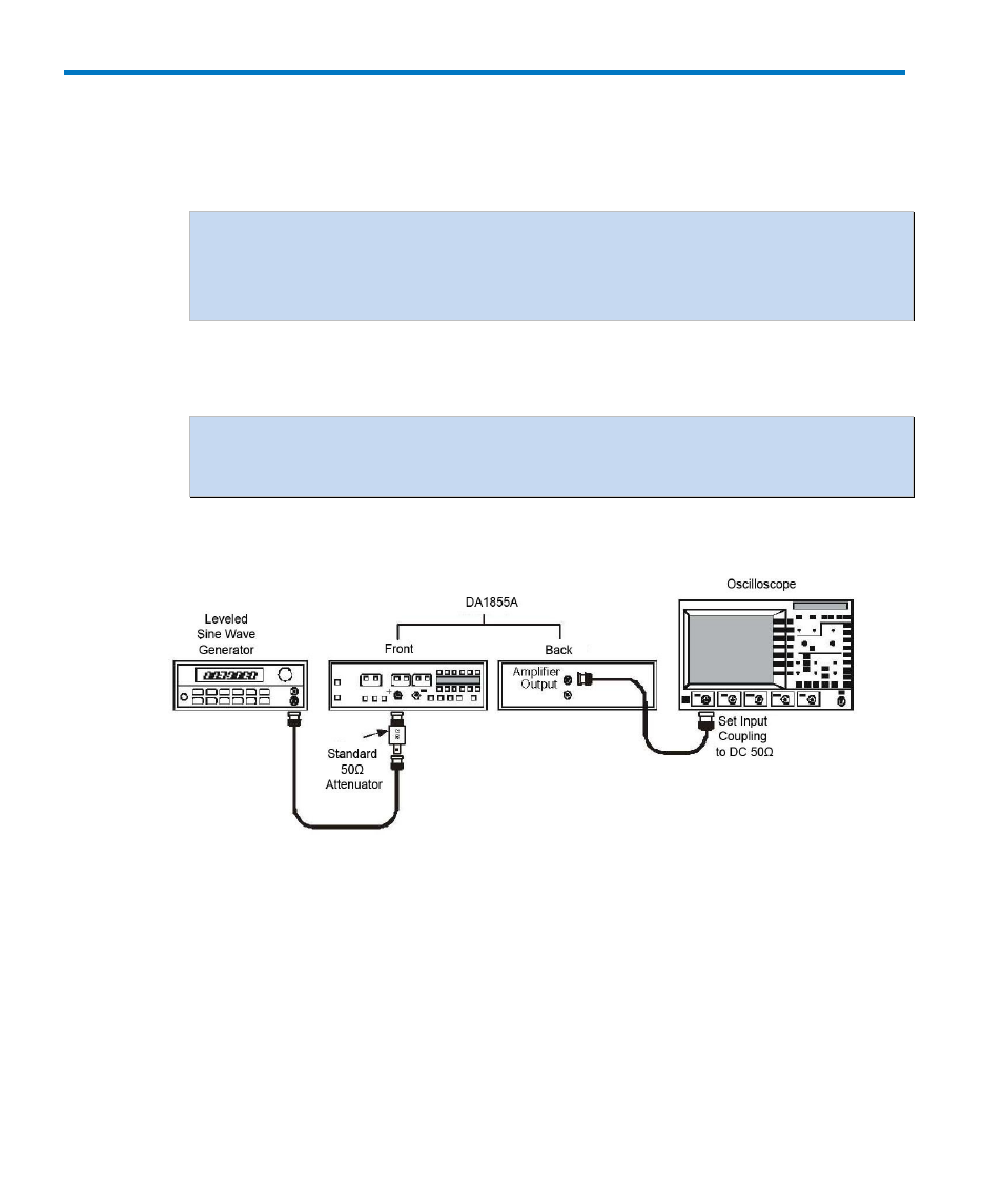
4. Check X1 Bandwidth and Calculate Rise Time
a. Connect the DA1855A AMPLIFIER OUTPUT to channel 1 of the oscilloscope.
b. Set the channel 1 input coupling to 50 Ω.
NOTE: If the oscilloscope does not have an internal 50
input termination, insert
the standard inline 50
termination between the cable and the oscilloscope input.
Use the standard wide bandwidth 50
termination. The precision termination is not
accurate at frequencies higher than 100 kHz.
c. Verify that the DA1855A GAIN is set to X1 and the ATTENUATOR to ÷10.
d. Connect a BNC cable to the output of the leveled sine wave generator.
NOTE: Many leveled sine wave generators, including the SG503, are calibrated only
when a special BNC cable is used on its output. Be sure to use a cable which is
specified for the generator.
e. Insert a standard 50 Ω termination on the free end of the cable and connect the
termination to the +INPUT of the DA1855A. Refer to Figure 16.
Figure 16, X1 Bandwidth Check Setup
f. Set the leveled sine wave generator output frequency to 50 kHz, and the amplitude
to approximately 300mVp-p.
g. Set the oscilloscope Volt/div to 50 mV/div and the time/div to 20 μsec/div.
Oscilloscope bandwidth to FULL. Triggering to Channel 1. Adjust the trigger level for
a stable display.
h. Adjust the leveled sine wave generator output for an amplitude of exactly 6
divisions on the oscilloscope.