Teledyne LeCroy DA1855A User Manual
Page 77
Operator’s Manual
922258-00 Rev A
71
j. Verify that the channel 1 input coupling is set to DC and 1MΩ.
k. Set the oscilloscope to display channel 1, the vertical sensitivity to 500mV/div,
timebase to 50 ns/div and trigger source to external ÷10. If necessary, adjust the
trigger level for a stable display.
l. Set the leveled sine wave generator frequency to 10 MHz.
m. Set the leveled sine wave generator output amplitude to exactly 2 Vp-p. (4 divisions
on the oscilloscope).
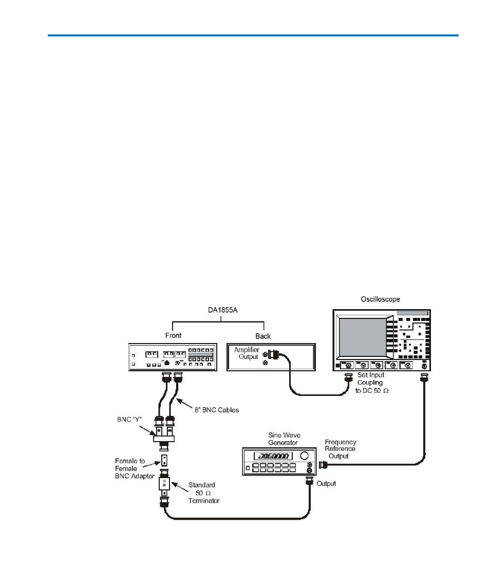
n. Remove the leveled sine wave generator output cable and termination from the
oscilloscope.
o. Attach to the 50 Ω termination a female to female BNC adapter, a BNC ‘Y’ and a 6”
BNC cable to each end of the BNC ‘Y’.
p. Set both the DA1855A +INPUT and –INPUT to DC.
q. Connect the two free ends of the 6” BNC cables to the DA1855A +INPUT and –
INPUT.
r. Reconnect the AMPLIFIER OUTPUT cable to channel 1 of the oscilloscope. Refer to
Figure 19, HF CMRR Check Setup
- 6Zi Rackmount (12 pages)
- HDO Oscilloscope Rackmount (14 pages)
- LSIB-1 Host Interfaces (44 pages)
- OC1021 Oscilloscope Cart (9 pages)
- OC1024 Oscilloscope Cart (10 pages)
- OC910 Oscilloscope Cart (2 pages)
- TTL-AUX-OUT (1 page)
- WaveJet Rackmount (1 page)
- Zi Oscilloscope Rackmount (12 pages)
- USB2-GPIB (12 pages)
- WM8Zi-2X80GS (2 pages)
- WR6ZI-8CH-SYNCH (6 pages)
- Zi Oscilloscope Synchronization ProBus Module (Zi-8CH-SYNCH) (16 pages)
- LogicStudio (42 pages)
- WaveSurfer MXs-B Getting Started Manual (126 pages)
- WaveSurfer MXs-B Quick Reference Guide (16 pages)
- X-STREAM OSCILLOSCOPES Remote Control (305 pages)
- WS-GPIB (12 pages)
- PXA125 (219 pages)
- PXD Series (42 pages)
- PXD222 (38 pages)
- Oscilloscope System Recovery (8 pages)
- LabMaster 9Zi-A (264 pages)
- LabMaster 10Zi Rackmount (8 pages)
- LabMaster 10Zi Getting Started Manual (236 pages)
- LabMaster 10Zi Operators Manual (198 pages)
- WaveAce 1000_2000 (108 pages)
- WaveAce 1000_2000 Remote Control (92 pages)
- WaveRunner Xi-A Quick Reference Guide (16 pages)
- WaveRunner XI SERIES Operator’s Manual (233 pages)
- WaveMaster Automation Command (667 pages)
- WaveMaster 8 Zi_Zi-A (190 pages)
- WaveMaster 8000A (46 pages)
- WavePro 7 Zi_Zi-A (188 pages)
- WaveExpert series Automation Manual (285 pages)
- WaveExpert 9000_NRO9000_SDA100G Getting Started Manual (50 pages)
- WaveExpert 100H Operators Manual (348 pages)
- WaveRunner Automation Command (460 pages)
- WaveRunner Xi-A Getting Started Manual (128 pages)
- WaveRunner 6 Zi and 12-Bit HRO Getting Started Manual (198 pages)
- WaveRunner 6 Zi Quick Reference Guide (20 pages)
- WaveRunner 6 Zi-ExtRef-IN_OUT (2 pages)
- WaveSurfer Automation Command (226 pages)
- HDO 4000 Getting Started Guide (48 pages)
- HDO Removable Hard Drive (2 pages)