Amplifier output, Operator’s manual, And v – Teledyne LeCroy DA1855A User Manual
Page 25
Operator’s Manual
922258-00 Rev A
19
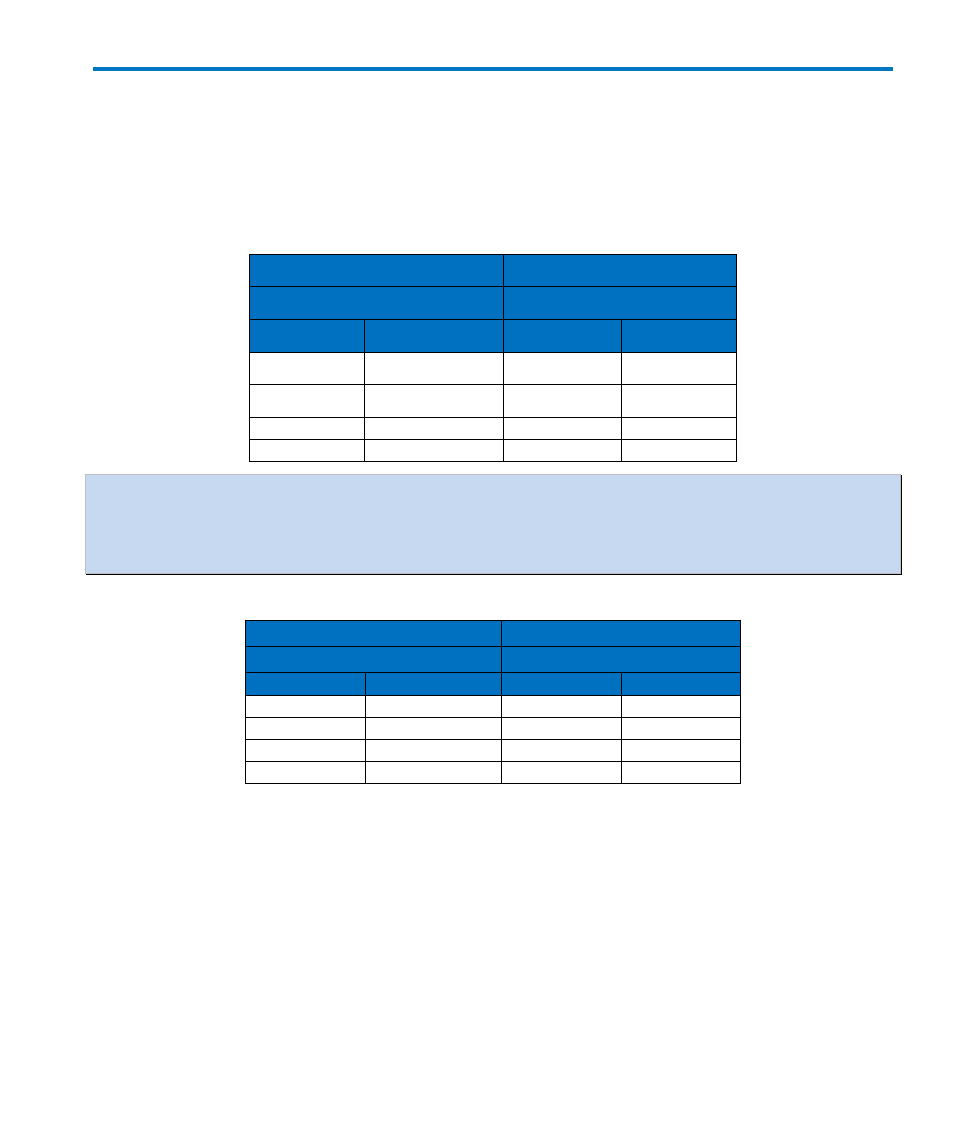
Table 2 and Table 3 will help the operator stay within the maximum input voltage limits and
understand the relationship between the actual voltage applied and the effective voltage. Effective
voltage is always referred to the input of the DA1855A or the probe tip if a probe is used. When
using probes, the maximum effective voltage range may be limited by the maximum voltage rating
of the probe.
Table 2, Effective Offset Range with ÷11 Probe
Front Panel
Effective Offset
Settings
Range
Gain
Attenuation
V
COMP
V
DIFF
X1
÷1
± 15.5 V
± 10 V
X1
÷10
± 155 V
± 100 V
X10
÷1
± 15.5 V
± 1 V
x10
÷10
± 155 V
± 10 V
NOTE: The effective voltage is always increased by the attenuator. It therefore follows that any
probe will increase the effective voltage of both V
COMP
and V
DIFF
by its attenuation factor.
For example, a probe with a 100X attenuation factor will increase the effective full scale range by
100.
Table 3, Effective Offset Range with ÷100 Probe
Front Panel
Effective Offset
Settings
Range with ÷100 Probe
Gain
Attenuation
V
COMP
V
DIFF
X1
÷1
± 1.55 kV
± 1 kV
X1
÷10
± 15.5 kV
± 10 kV
X10
÷1
± 1.55 kV
± 100 V
x10
÷10
± 15.5 kV
± 1 kV
Although the full scale range may be 10 kV or 15.5 kV, most probes have a much lower maximum
input voltage rating which must not be exceeded.
Amplifier Output
The AMPLIFIER OUTPUT BNC is intended to be used with an oscilloscope, spectrum analyzer or
instrument having a 50 Ω input resistance. The amplifier’s output impedance is 50 Ω. Without the 50
Ω load, the amplifier gain will be uncalibrated and will be approximately twice the amount indicated
on the front panel. Proper operation of the 1 MHz or 20 MHz bandwidth limit filters requires an
output load impedance of 50 Ω.