Teledyne LeCroy DA1855A User Manual
Page 80
DA1855A Differential Amplifier
74
922258-00 Rev A
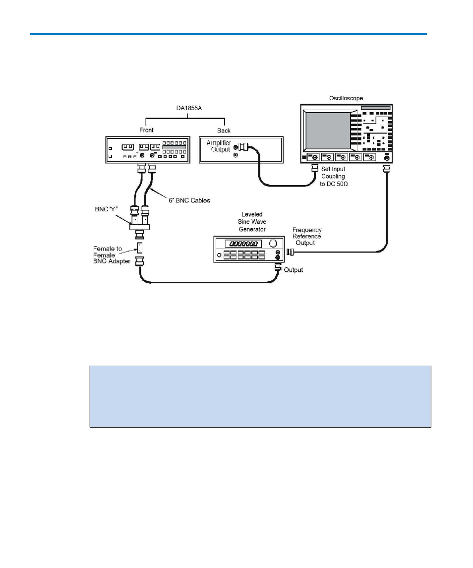
k. Set the oscilloscope to display channel 1, coupling to DC and impedance to 50 Ω and
the vertical sensitivity as necessary to measure the amplitude of the displayed
waveform. Refer to Figure 21
Figure 21, LF CMRR Check Setup
l. The displayed signal is the Common Mode Feedthrough. (Use the oscilloscope
ZOOM function and averaging if needed to increase the size of the displayed
waveform and to reduce noise.)
NOTE: This measurement needs to be made very carefully. The signal is only several
hundred μV in amplitude and measuring the peak to peak amplitude of this signal,
using oscilloscope measurement functions, may cause erroneous reading. Measure
only the amplitude of the common mode feedthrough, not the total value of the
signal plus noise.
m. Record the displayed ‘Common Mode Feedthrough at 70 Hz’ to two digit resolution
in the Test Record.
n. Calculate the Common Mode Gain by dividing the Common Mode Feedthrough (in
μV) by 20,000,000 μV. Record the result to two significant places as ’Common Mode
Gain at70 Hz’ in the Test Record. (Keep all of the leading zeros or use scientific
notation.)