Teledyne LeCroy DA1855A User Manual
Page 71
Operator’s Manual
922258-00 Rev A
65
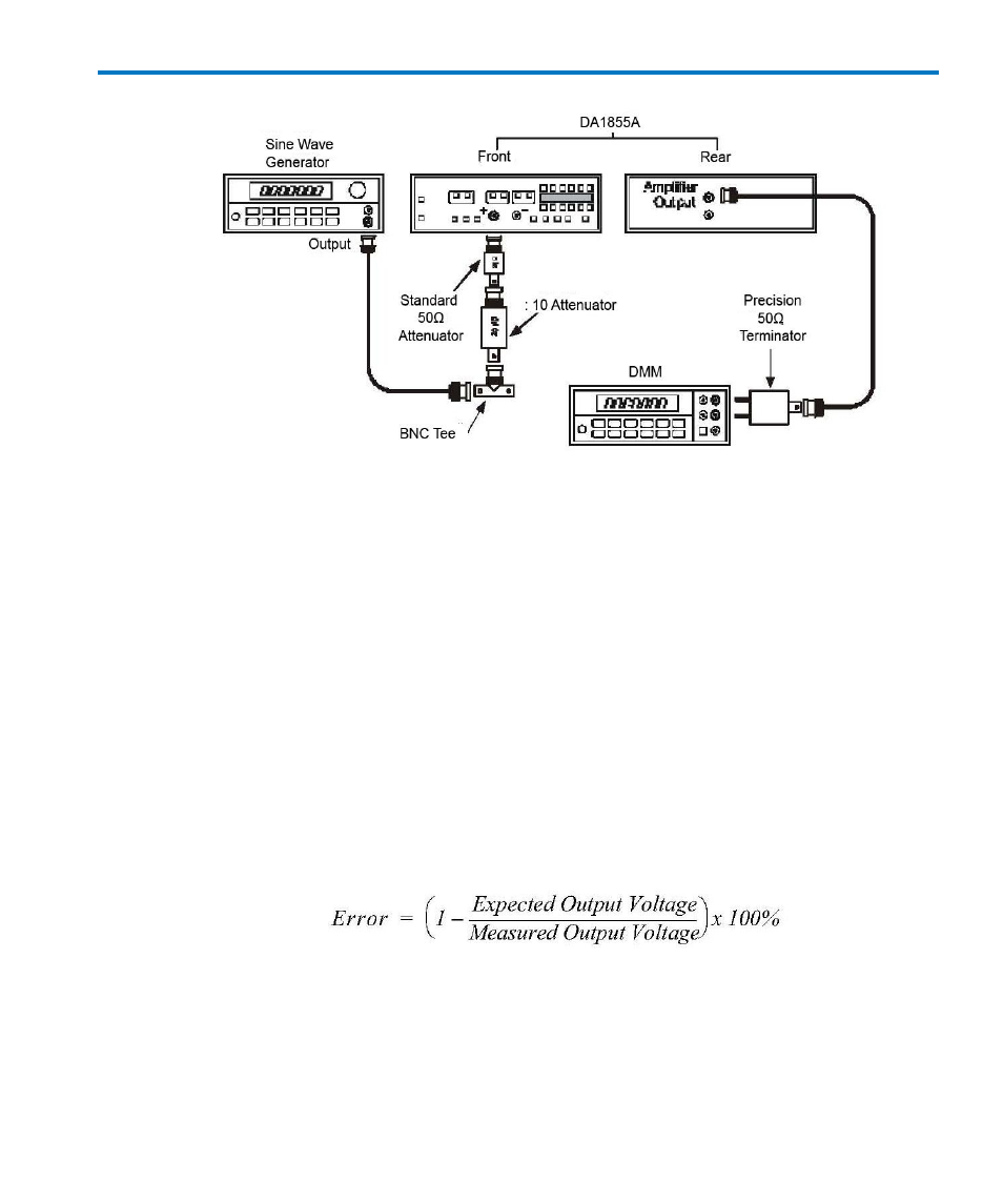
Figure 13, X10 Gain Accuracy Setup
v. Divide the sine wave generator output voltage recorded in step 2-q by the exact
attenuation factor recorded in step 2-l. This represents the actual voltage on the
input of the amplifier. Record the result as ‘Amplifier Input Voltage’ in the Test
Record.
w. Multiply the amplifier input voltage as recorded in step 2-v by 10.0 to obtain the
expected output voltage. Record the result to four digit resolution as ‘Expected
Amplifier Output Voltage’ in the Test Record.
x. After the DMM reading has stabilized, record the measured voltage to 100 μV
resolution as ‘Measured Amplifier Output Voltage’ in the Test Record.
y. Calculate the error by dividing the expected output voltage recorded in step 2-w by
the measured output voltage recorded in step 2-x. Subtract this ratio from 1 and
multiply by 100% to get the error in percent.
z. Record the calculated error to two decimal places (±0.xx%) inthe Test Record as ‘X10
Gain Error’. Check that the calculated error is less than ± 1%
- 6Zi Rackmount (12 pages)
- HDO Oscilloscope Rackmount (14 pages)
- LSIB-1 Host Interfaces (44 pages)
- OC1021 Oscilloscope Cart (9 pages)
- OC1024 Oscilloscope Cart (10 pages)
- OC910 Oscilloscope Cart (2 pages)
- TTL-AUX-OUT (1 page)
- WaveJet Rackmount (1 page)
- Zi Oscilloscope Rackmount (12 pages)
- USB2-GPIB (12 pages)
- WM8Zi-2X80GS (2 pages)
- WR6ZI-8CH-SYNCH (6 pages)
- Zi Oscilloscope Synchronization ProBus Module (Zi-8CH-SYNCH) (16 pages)
- LogicStudio (42 pages)
- WaveSurfer MXs-B Getting Started Manual (126 pages)
- WaveSurfer MXs-B Quick Reference Guide (16 pages)
- X-STREAM OSCILLOSCOPES Remote Control (305 pages)
- WS-GPIB (12 pages)
- PXA125 (219 pages)
- PXD Series (42 pages)
- PXD222 (38 pages)
- Oscilloscope System Recovery (8 pages)
- LabMaster 9Zi-A (264 pages)
- LabMaster 10Zi Rackmount (8 pages)
- LabMaster 10Zi Getting Started Manual (236 pages)
- LabMaster 10Zi Operators Manual (198 pages)
- WaveAce 1000_2000 (108 pages)
- WaveAce 1000_2000 Remote Control (92 pages)
- WaveRunner Xi-A Quick Reference Guide (16 pages)
- WaveRunner XI SERIES Operator’s Manual (233 pages)
- WaveMaster Automation Command (667 pages)
- WaveMaster 8 Zi_Zi-A (190 pages)
- WaveMaster 8000A (46 pages)
- WavePro 7 Zi_Zi-A (188 pages)
- WaveExpert series Automation Manual (285 pages)
- WaveExpert 9000_NRO9000_SDA100G Getting Started Manual (50 pages)
- WaveExpert 100H Operators Manual (348 pages)
- WaveRunner Automation Command (460 pages)
- WaveRunner Xi-A Getting Started Manual (128 pages)
- WaveRunner 6 Zi and 12-Bit HRO Getting Started Manual (198 pages)
- WaveRunner 6 Zi Quick Reference Guide (20 pages)
- WaveRunner 6 Zi-ExtRef-IN_OUT (2 pages)
- WaveSurfer Automation Command (226 pages)
- HDO 4000 Getting Started Guide (48 pages)
- HDO Removable Hard Drive (2 pages)