Setting up the oscilloscope with probus interface – Teledyne LeCroy DA1855A User Manual
Page 31
Operator’s Manual
922258-00 Rev A
25
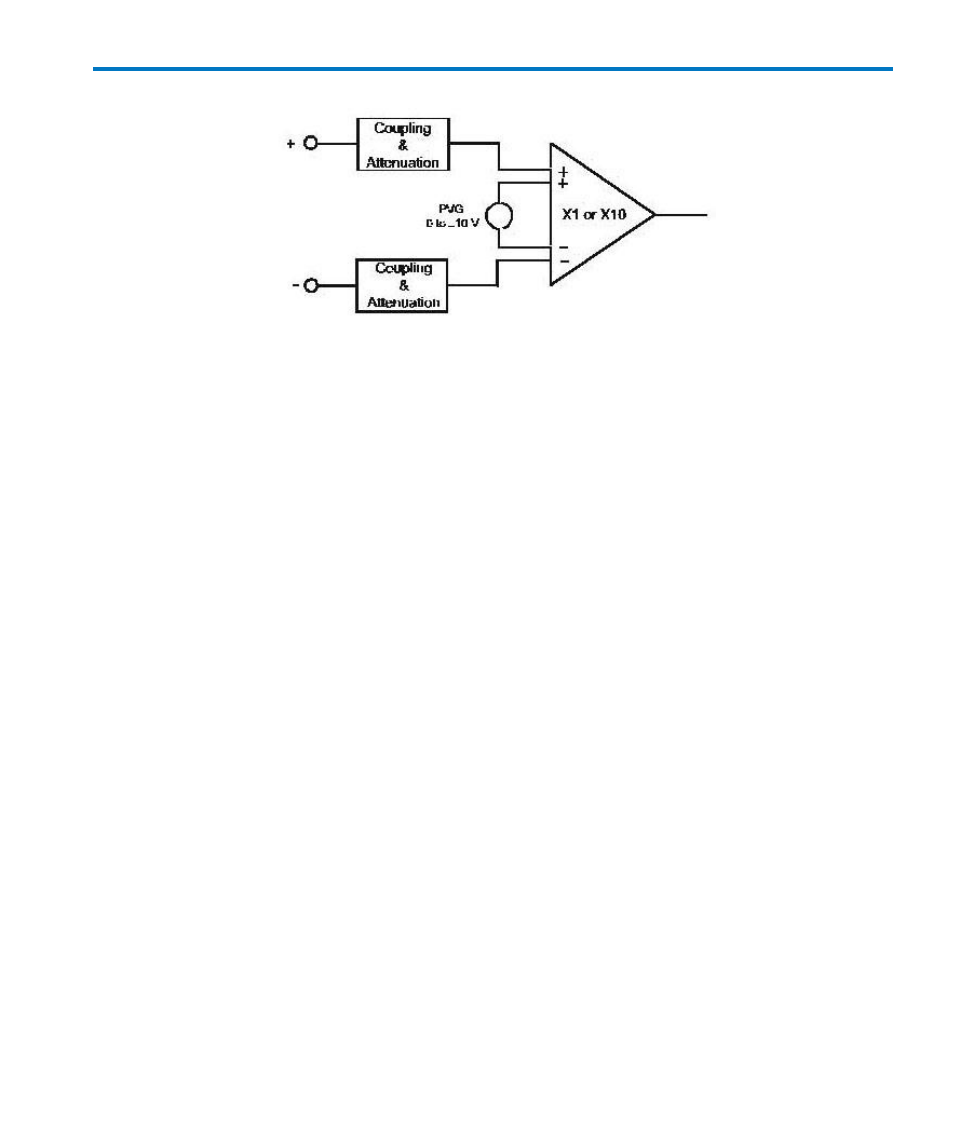
Figure 2, Block Diagram V
DIFF
Mode.
Setting Up the Oscilloscope with ProBus Interface
Connect the RJ-45 type connector of the ProBus interface cable to the REMOTE connector and one
end of the BNC cable to the AMPLIFIER OUTPUT on the rear panel of the DA1855A and the other
end of the BNC cable to the ProBus connector. Connect the ProBus connector to any vertical
channel and, if necessary, press the Front Panel channel button to turn on the channel.
Switch the power switch located on the DA1855A’s rear panel to ON and observe the front panel
indicators. Initially, each indicator light will be ON and the red OVERLOAD indicator will be ON as
well. All segments in the Precision Voltage Generator display will be ON. The +INPUT and –INPUT
Coupling Indicators will switch to OFF while the amplifier performs the Auto Zero function and back
to the original setting. After approximately 3 seconds from turn on, the DA1855A will return to the
settings in effect when the power was last turned off. The oscilloscope’s input impedance has been
set to 50 Ω automatically through the ProBus interface, the trace has been centered and all
DA1855A front panel controls are locked out.