IAI America XSEL Ethernet User Manual
Page 25
- 19 -
4.4.1
Little Endian Operation
The default endian mode of DI/DO operation commands of the X-SEL controller is the little endian.
In the little endian mode, the remote I/O field accessed via word operation with an IN, INB, OUT or
OUTB command of the X-SEL controller will have its upper and lower bytes reversed in relation to
the X-SEL data if the same field is word-accessed via Modbus/TCP.
The following examples are based on 256-bit assignments from the head DO number (= 300) in
X-SEL as Modbus/TCP remote I/Os.
(Note) Remote I/Os can be defined only as consecutive numbers.
The assignable head number must satisfy: 300 + 8n (31
n 0).
The total number of assignable bits must satisfy: m + n < 32 & 32
m, where m represents
the number of assigned remote I/O bytes.
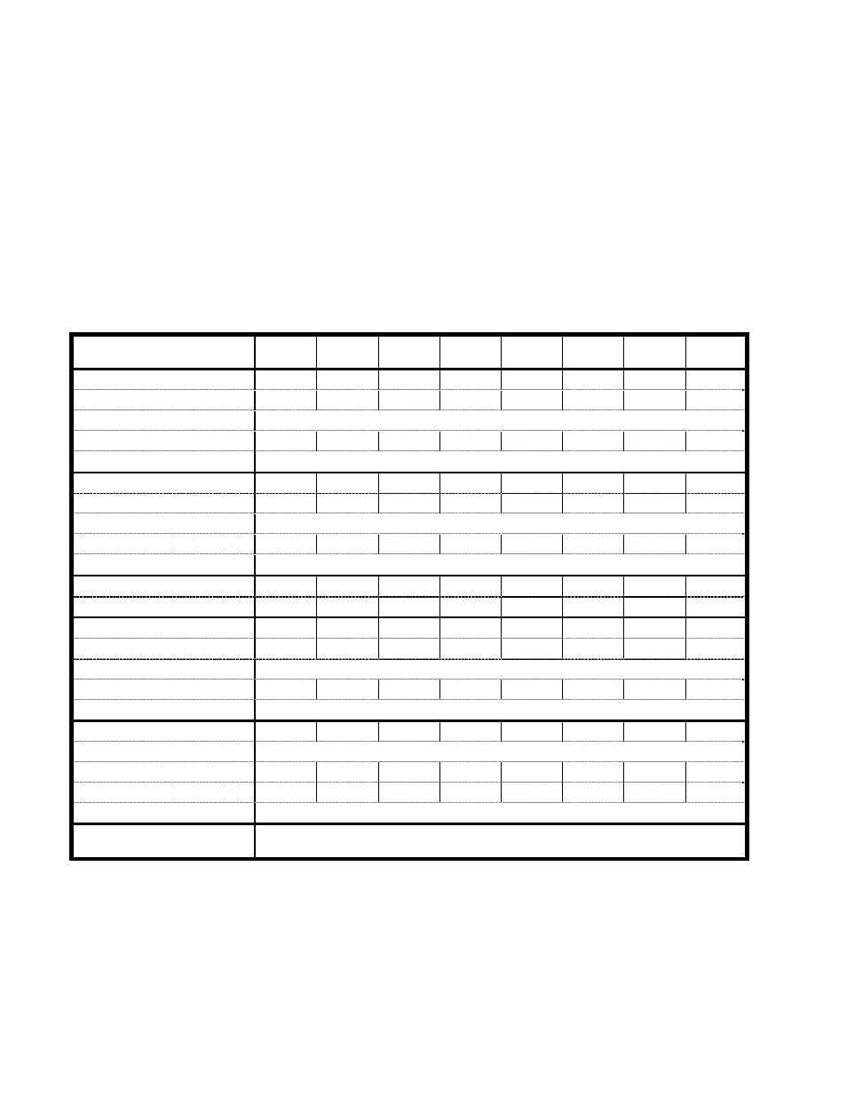
[Modbus/TCP input areas (assignment of X-SEL DO area 300 onward)]
Address
BIT7
(MSB)
6 5 4 3 2 1
0
(LSB)
X-SEL
DO
307 306 305 304 303 302 301 300
Modbus/TCP
bit
address
0 1 2 3 4 5 6 7
Modbus/TCP word address
0 Lower byte
Modbus input status
10001
10002
10003
10004
10005
10006
10007
10008
Modbus input register
30001 Lower byte
X-SEL
DO
315 314 313 314 315 310 309 308
Modbus/TCP bit address
8
9
10
11
12
13
14
15
Modbus/TCP word address
0 Upper byte
Modbus input status
10009
10010
10011
10012
10013
10014
10015
10016
Modbus input register
30001 Upper byte
:
:
X-SEL
DO
547 546 545 544 543 542 541 540
Modbus/TCP
bit
address 240 241 242 243 244 245 246 247
Modbus/TCP word address
15 Lower byte
Modbus input status
10248
10249
10250
10251
10252
10253
10254
10255
Modbus input register
30016 Lower byte
X-SEL
DO
555 554 553 552 551 550 549 548
Modbus/TCP bit address
15 Upper byte
Modbus/TCP
word
address
248 249 250 251 252 253 254 255
Modbus input status
10249
10250
10251
10252
10253
10254
10255
10256
Modbus input register
30016 Upper byte
Cannot be used
Input status:
input discretes
single bit, provided by an I/O system, read-only
Output coil:
output discretes
single bit, alterable by an application program, read-write
Input register:
input registers
16-bit quantity, provided by an I/O system, read-only
Output register: output registers
16-bit quantity, alterable by an application program, read-write
The output areas are described on the next page.