Notes on operation, 1 load applied to the actuator – IAI America NS User Manual
Page 52
38
10. Notes on Operation
10. Notes on Operation
10.1
Load Applied to the Actuator
x The load specified in the specification table must not be exceeded.
In particular, pay attention to the moments applied to the slider, allowable overhang length and loaded
mass.
x If the actuator is used as the Y-axis in a cantilever X-Y robot, the base becomes vulnerable to
deformation. Accordingly, keep the Ma and Mc moments to one half the rated moment or below. (Refer
to the figure below.)
Small type
SXMS, SXMM, SZMS, SZMM
Allowable load moments
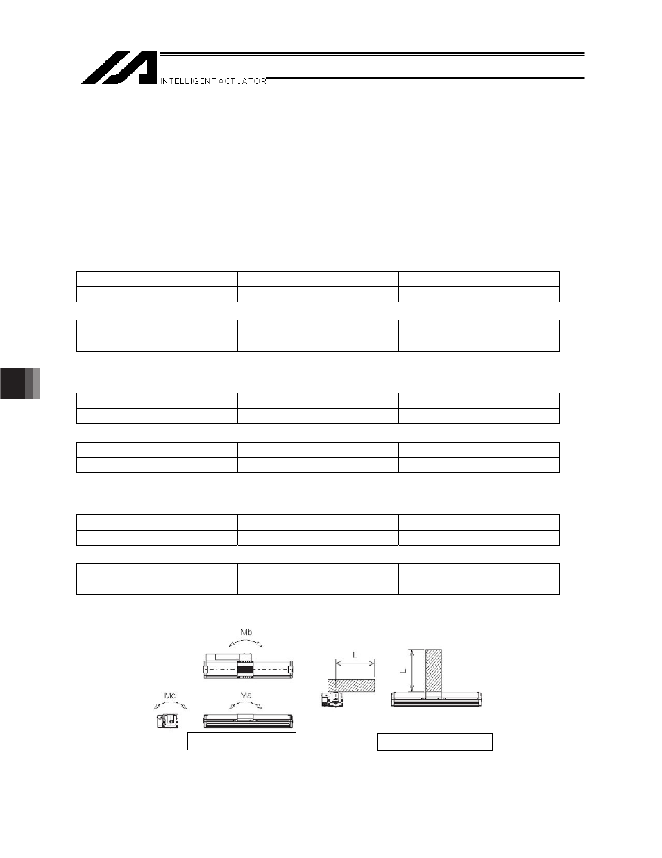
Ma
Mb
Mc
28.4 N
m (2.9 kgfm)
40.2 N
m (4.1 kgfwm)
65.7 N
m (6.7 kgfwm)
Allowable overhang lengths
Ma direction
Mb direction
Mc direction
450 mm max.
450 mm max.
450 mm max.
Medium type MXMS, MXMM, MXMXS, MZMS, MZMM
Allowable load moments
Ma
Mb
Mc
69.6 N
m (7.1 kgfm)
99.0 N
m (10.1 kgfwm) 161.7
N
m (16.5 kgfwm)
Allowable overhang lengths
Ma direction
Mb direction
Mc direction
600 mm max.
600 mm max.
600 mm max.
Large type
LXMS, LXMM, LXMXS, LZMS, LZMM
Allowable load moments
Ma
Mb
Mc
104.9 N
m (10.7 kgfm) 149.9
N
m (15.3 kgfwm) 248.9
N
m (25.4 kgfwm)
Allowable overhang lengths
Ma direction
Mb direction
Mc direction
750 max.
750 max.
750 max.
z The allowable overhang lengths are based on a configuration where the center of gravity of the
installed article is positioned at one half the overhang length.
Application of an excessive load moment may lead to unwanted outcomes such as a shorter service life of
the guide. If the overhang length exceeds the allowable value, vibration may occur or the service life of the
guide may be negatively affected.
Mb/Mc directions
Ma direction
Directions of moment
Directions of overhang