Securitron SAM2-24 User Manual
Page 8
PN# 500-10450
Page 8
Rev. B, 02/12
5.7.2 Strike Level Adjustment Testing (Energized)
Energized adjustment testing of the strike height is important for proper door/lock operations.
This adjustment should be performed after the de-energized adjustment, outlined in Section
5.7.1. With the door closed and the Magnalock de-energized, apply power to the Magnalock.
The strike should be pulled up against the Magnalock face. De-energize the Magnalock and the
strike should return to the previously adjusted height. This function should be tested several
times to insure that the strike level adjustment is correct.
If the strike is not pulled up to the face of the Magnalock, the strike is to far away from the
Magnalock. Make small 1/4 turn adjustments to the strike screws until the correct level and
clearances are obtained for proper function.
A second test should be performed with the door starting from the opened position. Apply
power to the Magnalock and then close the door under normal operations. The strike should be
attracted to the Magnalock, but the strike and the interference buttons should pass completely
into the locking position to secure the door. Test this operation several times to ensure
consistent operation of the Magnalock/strike installation.
WHEN THE MAGNALOCK IS ENERGIZED FOR A CONTINUOUS DUTY MODE, THE
ADJUSTMENTS MADE MAKE IT A POSITIVE LOCKING MODE FOR CONTROLLED ACCESS.
IF THE MAGNALOCK IS SET FOR CONTINUOUS DUTY, THE EXIT REQUEST ALLOWS THE
STRIKE TO DROP AWAY AND CLEAR FOR SMOOTH EGRESS. WHEN THE MAGNALOCK
BECOMES ENERGIZED, WHILE THE DOOR IS STILL IN THE OPENED POSITION, THE
DOOR CLOSING AND LOCKING FEATURES WILL STILL FUNCTION, WHEN THE DOOR
CLOSES, THE STRIKE REALIGNS BACK TO THE LOCKING POSITION TO SECURE. THERE
SHOULD BE NO INTERFERENCES THAT PREVENT THE DOOR FROM CLOSING OR
BECOMING SECURE.
6 ELECTRICAL INSTALLATION
6.1 General Characteristics
The Magnalock is a low current load device using specialized internal circuitry. The normal
characteristic of an inductive load, such as inductive kick-back, is not present. See Section 2
for more information.
6.2 Electrical Standards
DC voltage, full-wave rectified, must be provided for proper operation of the Magnalock. The red
wire receives +24VDC, and the black wire, 0 Volts (negative). If the Magnalock is connected
with reverse polarity, it will not operate. The SAM2-24 Magnalock is a single voltage (24VDC
only) device.
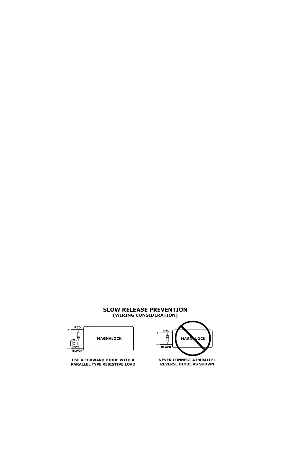
6.3 Poor Release Characteristics
The SAM2 Magnalock is designed with quick release operation. Wiring errors may cause a
Magnalock to release slowly. Figure 11 illustrates a parallel installation of a resistive load
(correct). Figure 12 illustrates a parallel reverse diode (incorrect).
Figure
11
Figure
12