Securitron SAM2-24 User Manual
Page 5
PN# 500-10450
Page 5
Rev. B, 02/12
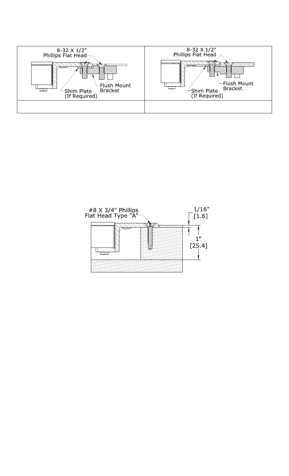
mounting bracket and the flush mount bracket in order to raise the Magnalock above the frame
surface.
Figure 4 - Flush mount bracket mounting
(thin wall frame)
Figure 5 - Flush mount bracket mounting
(thick wall frame)
APPLY THE PROVIDED THREAD LOCKING COMPOUND TO ALL MOUNTING SCREW
THREADS.
5.5.2 Solid Wood Door Frames
Prepare the door frame in accordance with Section 5.4.1.
Place the Magnalock into the cutout area to ensure proper fit. As necessary, perform any filing
or chiseling necessary to ensure the mortised fit. Ensure all necessary holes required to mount
the Magnalock into place as indicated on the template have been provided. The depth of the
mortise cutout is important for proper fit. The minimum depth of the cutout is noted in Figure
6 below and includes enough distance for the required recess depth of 1/16” [1.6mm] of the
mounting brackets. Install the Magnalock using the wood mounting screws as shown in Figure
6.
Figure 6 - Wood frame lock bracket mounting
5.6 Mounting the Strike Assembly
The strike assembly mounting method varies with the type of door being used. The included
template provides preparation and installation information for the various types of doors. The
following sections describe the door type and installation procedures.
The strike bracket assembly has been designed with adjustment features which are intended to
help accurately install and adjust the strike assembly for proper operation. The two L-shaped
end brackets and the idle bracket of the assembly are serrated to provide a secure locking
adjustment of the height of the strike in the door edge. The end brackets have obround slots to
limit the adjustment travel and to support the structure of the assembly. By loosening the
screws at each end, the brackets can be adjusted to the desired mounting height.
The serrations on the brackets are .050” [1.3mm] apart which matches the screw thread pitch
distance that mounts the strike. This feature will be explained during the final adjustment in
Section 5.7. These end brackets may also be inverted to provide for deeper mounting
configurations. See Figure 7 and Figure 8 for adjustable ranges and mounting methods.
THE POSITION OF THE CENTERLINE OF THE STRIKE ASSEMBLY IS CRITICALLY
RELATED TO THE CENTERLINE OF THE MAGNALOCK LOCATION.
5.6.1 Hollow Metal Door (Flush Top)