Securitron FSUNL_Series User Manual
Power supply c, Nc no, Unl-24 no normally open switch fsunl-24
Securitron Magnalock Corp.
www.securitron.com
ASSA ABLOY, the global leader
Tel
800.624.5625
in door opening solutions
© Copyright, 2011, all rights reserved
PN# 500-19200
Page 1
Rev. G, 08/11
INSTALLATION AND OPERATING INSTRUCTIONS
Fail Safe UnLatch FSUNL Series
1. INTRODUCTION
Securitron’s FSUNL-12 and FSUNL-24 are designed to work in conjunction with the UnLatch
family of products (UNL Series or MUNL Series). When interfaced with any UnLatch device the
FSUNL will allow the user to select specifically between “Fail Safe” or “Fail Secure” operation.
2. SPECIFICATIONS
Enclosure dimensions: 8”x6”x3” (inches) - Jumper selectable Fail Safe or Fail Secure operation.
Inrush current on power up:
Standby current:
1.45Amps for 3 seconds at 12VDC
90mA @ 12VDC at rest
1.2Amps for 3 seconds at 24VDC
140mA @ 24VDC at rest
Voltage Threshold: 12VDC
Voltage Threshold: 24VDC
Fail safe latch release @ 9.8VDC
Fail safe latch release @ 20VDC
Fail safe latch re-secure @ 10.8VDC
Fail safe latch re-secure @ 22.5VDC
3. RECOMMENDED TOOLS
Standard and Phillips Screwdriver
Drill Motor (optional)
Crimping Tool and Connectors
Digital Multi-Meter or Volt Ohm Meter
Wire Stripper
4. INSTALLATION INSTRUCTIONS
The FSUNL should be mounted indoors in an area protected from tampering (i.e. electronics
closet or above the drop ceiling at the opening) if possible. The board and enclosure can also be
surface mounted to the wall above the opening. For the most attractive surface installation the
cabling to the device should be run through the wire access port on the back of the enclosure
right into the wall. If this is inconvenient, or esthetics is not a concern the knock out on either
side of the enclosure (cover) can also be used.
5. OPERATIONAL INSTRUCTIONS
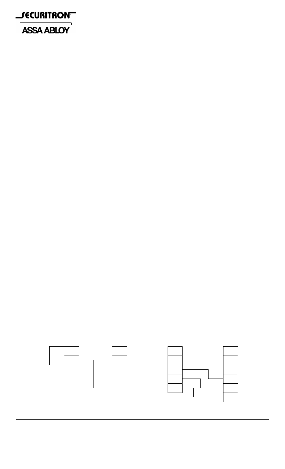
Once wired, as shown in the diagram below, the FSUNL will operate in the following manner: 1)
If the jumper selector is set to Fail Safe operation and the power to the system is lost the
capacitor energy reservoir will discharge and the trigger input on the UNL/MUNL will be initiated
driving the device through it’s cycle to the point were the door is unlocked. 2) If the jumper
selector is set to Fail Secure and power to the system is lost the capacitor energy reservoir will
discharge and the trigger input on the UNL/MUNL will be initiated driving the device through it’s
cycle to the point were the door is locked.
Definition of terminal strip:
+IN = Positive 12 or 24VDC continues input +OUT = Positive 12 or 24VDC continues to UNL
TI = Trigger input from external switch
- = Negative 0VDC continues reference
TO = Trigger out to UNL
Basic Wiring Diagram (Example24V):
-
+
120
VAC
IN
VDC
OUT
POWER SUPPLY
C
TRIG
NC
NO
+
-
UNL-24
NO
NORMALLY
OPEN SWITCH
FSUNL-24
+IN
TI
+OUT
-
TO
NO
RED
BLK
ORG
WARNING CAPACITOR SHOCK HAZARD!