Securitron SAM2-24 User Manual
Page 10
PN# 500-10450
Page 10
Rev. B, 02/12
APPENDIX A
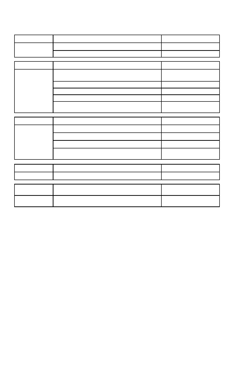
Troubleshooting
Problem
Lock Does Not Generate a Magnetic Field
Points of Reference
Check for specified voltage at Magnalock Section
2
Solution
Check for specified current draw at Magnalock
Section 2
Problem
Reduced Holding Force
Points of Reference
Check DC power source is Full-Wave Rectified
(Half-wave Rectifier or AC Power unacceptable)
Section 6.2
Check for specified voltage at Magnalock Section
2
Check for specified current draw at Magnalock
Section 2
Check strike mounting for proper installation
Sections 5.6-5.7
Solution
Check the Magnalock and strike for obstructions
and that contact surfaces are properly cleaned
Section 7
Problem
The Magnalock Does Not Release
Points of Reference
Make sure no voltage is present at Magnalock
Section 2
Make sure the Magnalock is not drawing current
Section 2
Check if the strike is sticky and hard to release
Section 7
Solution
Check the Magnalock and strike for obstructions
and that contact surfaces are properly cleaned
Section 7
Problem
The Magnalock is Dirty or Rusty
Points of Reference
Solution
Improper cleaning – Maintenance Equipment
Section 7
Problem
Electronic Noise Interference with
Access Control System
Points of Reference
Solution
Check for voltage from Magnalock to door frame.
There should be no voltage present.
Section 2
IF PROBLEMS PERSIST CALL SECURITRON TOLL FREE
(800) MAG-LOCK
(800) 624-5625
Appendix B
Wire Gauge Factoring
1.1 Remote Power Supply
The Magnalock requires adequate voltage and current for proper operation.
Resistance is created by the length and gauge (size) of the wire being used.
An accurate estimated distance from the power supply to the opening is crucial.
For superior operation the correct size gauge wire must be used.
The devices used operate the best with the least amount of resistance on the source.
Using the correct gauge wires protects against large voltage and current (load) losses.
The gauge is determined by the wire distance, voltage and current of all devices.
1.2 Determining Wire Gauge
Follow Example A (24VDC system) below.
Use Table 1 to choose the correct wire gauge for the application.