E-Mon E-PS-A-RTU-N User Manual
Page 16
Chapter 2 Installation
Remote Display
I N S T A L L A T I O N
16
PowerSmart+ Advanced Power Quality Meter
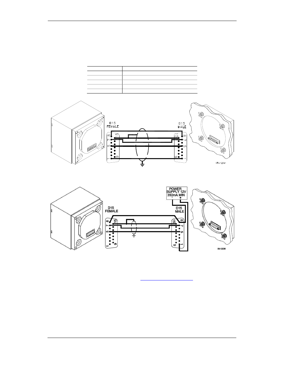
At distances of up to 100 m, the display receives power through the communication cable
directly from the meter. Connect pins 1 and 8 on both sides as shown in Figure 2-13.
At distances above 100 m, supply power from a separate 12V DC power source (a 12V
AC/DC adapter can be used). Connect the positive wire to pin 1 and the negative wire to
pin 8 as shown in Figure 2-14.
Pin
Signal
1
+12V
5
RS-485 + (plus)
7
RS-485 – (minus)
8
GND
15
Chassis ground
Figure 2-13 Self-powered remote display connection
Figure 2-14 Remote display powered from a 12V DC power source
If required, the remote display may be connected to one of the regular meter ports COM1
or COM2 via a three-wire RS-485 communication cable using a separate 12V DC power
source as shown in Figure 2-14. See
Communications Connections
for connector pin-outs
and connection diagrams. The meter port settings must be as follows: Modbus RTU
protocol, RS-485 interface, 19200 baud, 8-bits/no parity.