PASCO PS-2006 GLX Power Amplifier User Manual
Page 17
®
P S - 2 0 0 6 G L X P o w e r A m p l i f i e r
S a m p l e E x p e r i m e n t s : R L C C i r c u i t
15
e.
From the Graphs menu, select Scope Mode.
f.
Press to set the trigger for a rising edge at 0 V.
g.
From the Tools menu (
), select Power Amp Config.
The Graph screen should now look similar to Figure 5.
Procedure
1.
Turn on the output (if it is not already on).
2.
Press
to start displaying live scope traces.
3.
In the Power Amp Config panel, set the output frequency to the cir-
cuit’s resonant frequency (which you found in Part I).
4.
Adjust the scale (
, or ) to display a few full cycles.
5.
Write down the approximate phase relationship between voltage
and current.
6.
Change the output frequency to 1/4 of the resonant frequency.
Repeat steps 4 and 5.
7.
Change the output frequency to 4 times the resonant frequency.
Repeat steps 4 and 5 again.
Analysis
When are voltage and current in phase? When does current lead volt-
age? When does current lag voltage?
Further Study
•
Repeat the experiment with a different value of R, C, or L.
•
While watching voltage and current in the scope-mode graph,
change L by moving the metal core in the coil. Observe the effect
on the current amplitude and phase.
•
Repeat the experiment with a parallel RLC circuit.
•
Create an RLC circuit with as little resistance as possible and low
capacitance (about 10
µF). Drive the circuit with a square wave to
observe the circuit “ringing.” Vary L or C to change the frequency.
Vary R to change the damping.
F3
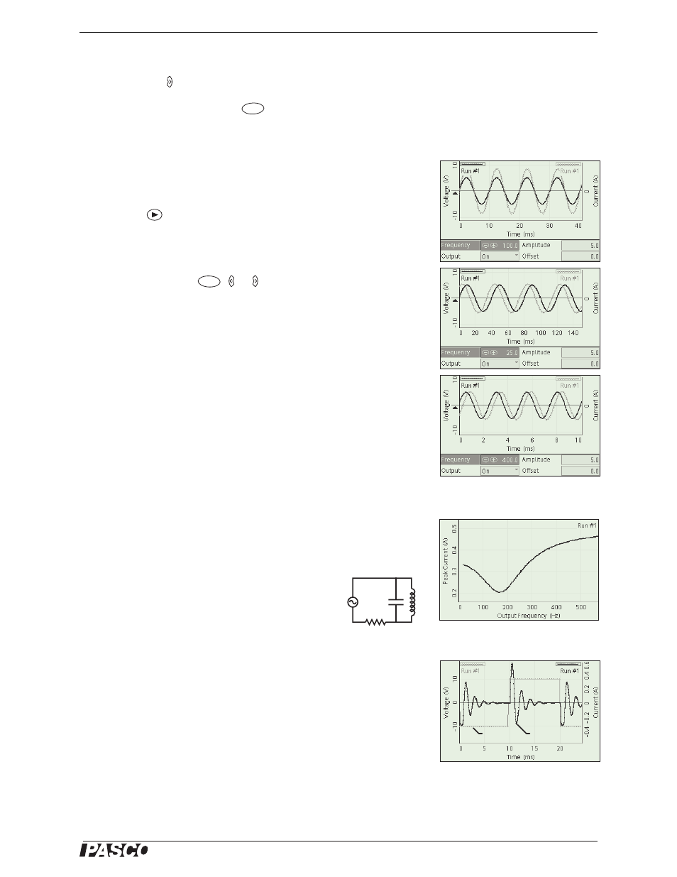
Figure 6: Typical Data
F2
Figure 7: Parallel RLC Data
Voltage
Current
Figure 8: Ringing