7 checking the communication setup – Micromod MOD: 30ML Controller Operation and Maintenance Training Manual User Manual
Page 10
Training Manual
MOD 30ML Front Face Familiarization Lab
1 - 8
1.4.7 Checking the Communication setup
Objective: Determine the Modbus address and communication parameters of this
instrument
Step Procedure
Comments
1.
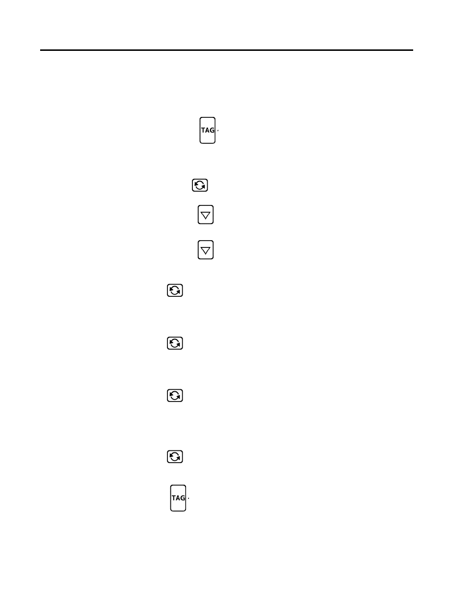
Press and hold the TAG key
Line 6 changes to display DEV STAT (device
status).
This is the start of the Status and Configuration
menus.
The Remote Local (R/L) and SCROLL keys now
function as “previous” PRV and “next” NXT keys.
2.
Press the NXT (scroll) key
SETUP appears on the bottom line, with a down
arrow indicating there are sub-menus
3.
Press the DOWN arrow key
The top of the display indicates SETUP BI COMM
(Set up built-in communications) with a down arrow
indicating there are further sub-menus
4.
Press the DOWN arrow key
The top of the display reads BI MSC 1 ADDRESS
(built-in Modbus serial port 1 address) and the
Modbus address for the built-in communication port
is shown on the bottom line.
5.
Press the NXT key
The top of the display changes to BI MSC 1
BAUDRATE and the baud rate is shown on the
bottom line. Dual arrows indicate that the
baud rate may be changed. Change the baud rate
to 38400
6.
Press the NXT key
The top of the display changes to BI MSC 1
PARITY and the parity is shown on the bottom line.
Dual arrows indicate that the parity may be
changed, however, for most applications you
should leave this at default of NONE.
7.
Press the NXT key
The top of the display changes to BI MSC 1
STOPBITS and the number of stop bits is shown
on the bottom line. Dual arrows indicate
that the number of stop bits may be changed,
however, for most applications you should leave
this at default of 1.
8.
Press the NXT key
The top of the display changes to BI MSC 1
ENABLED. This tells you that the Modbus
communications have been enabled. This occurred
during the download.
9.
Press the TAG key
This will return you to the beginning of the device
status displays
10.
Press the TAG key again
This will return you to the FIC-100 loop display
11.
Record the communication information for this instrument in the next table.