Micromod Micro-DCI: 53ML5100A LOADING STATION User Manual
Page 9
Directly beneath the horizontal keypad and concealed behind the front panel pull-down door is the
RS-232 Configuration Port. This port provides instrument access to the database for alternative
methods, other than using the front panel push buttons in engineering mode, to input selections
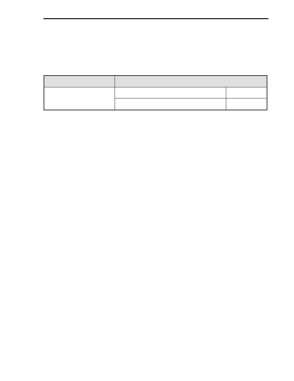
into the database for the operator displays. Alternative methods for loading or altering the instru-
ment database are summarized as follows:
F&P Hand Held Configurer
(Procedure in Section 3)
F&P Products* running on a Personal Computer
Software Package Reference
P/N 6988182U01 or
53HC3300 software package using
MC5FIG.EXE configuration program.
IB 53HC3300
P/N 6988182U02 with storage
cartridge capabilities.
53WS5000 software package using the
configuration program.
IB 53WS5000
*Although this instrument does not have network capabilities, it can be configured via the front
panel RS-232 Configuration Port with F&P network products.
At the opposite end of the instrument case from the configuration port is the rear terminal board
which has two pin socket terminal strips (TB1 and TB2). As illustrated in Figure 1-2, the connec-
tors can be removed from the terminal strips to facilitate easier signal and power wiring when the in-
strument is being installed. To ensure proper mating, only one side of the strips and connectors is
scalloped and the connectors are keyed. Also, as a further precaution, the signal connectors that
mate with the 22 pin terminal strip (TB1) are not the same size, as one has 12 screw lugs and the
other has 10 screw lugs.
Within the instrument case is the internal power supply. The internal power supply provides
power to the main board and output power for transmitters (24-26 V dc, 80 mA total available out-
put for instrument and transmitters).
Also within the instrument case is the main printed circuit board which has the necessary cir-
cuitry, firmware, and database for the Manual Loading Station functionality. The main board has
an embedded microcontroller Application Specific Integrated Circuit (ASIC) that is surface
mounted. The PROM element and individual components are through-hole mounted.
A simplified input/output diagram of the Manual Loading Station is provided in the upper left cor-
ner of Figure 1-2. As illustrated in the figure, the instrument can accept two Analog Input signals
(ANI0 and ANI1 ) which are digitized as operands for firmware interpretation and displayed as
process variables. Each ANI has a square root extractor and can accept linear or squared signals
of 0-20 mA (0-5 V) or 4-20 mA (1-5 V). The instrument also provides two Analog Output signals
(ANO0 and ANO1) that can be individually selected and manually controlled using the front panel
push buttons.
All of the selectable entries for the Manual Loading Station are parameter entries to the database.
The database is subdivided into modules composed of datapoints that are accessed by the instruc-
tion code as the instrument performs its functions. The database allows instrument functionality to
be refined to specific process applications, as display attributes can be altered and input/output sig-
nal characteristics can be defined. A datapoint location is represented as an alphanumeric ad-
dress, such as L472, which is the 0-20 mA Output select for ANO0. (When L472 is configured with
a 0, the ANO0 output range is 4-20 mA; when L472 is configured with a 1, the ANO0 output range
is 0-20 mA.) Datapoints are specified parenthetically in the illustration call-outs of Section 3 where
the displays are described in detail. There are also illustrated procedures provided in Section 3
that show how a datapoint is displayed and configured. Definitions for all of the Manual Loading
Station datapoints are provided in Section 4 and listed in alphanumeric order in Appendix A.
Section 1. Introduction
1-5