3 4.3 configuring the database modules, 3 configuring the database modules, Table 4-2. database modules – Micromod Micro-DCI: 53ML5100A LOADING STATION User Manual
Page 41
4.3 CONFIGURING THE DATABASE MODULES
The datapoints in the database modules must be changed to reflect required alterations in the fac-
tory standard configuration or when the instrument is re-configured. There are generally two data-
point parameter types contained in the four database modules. The parameter types affect
display indications and input-output signals. The four database modules are described in Table 4-
2. Although it is not an absolute criterion, it is assumed the modules will be configured in the table
Item order.
Table 4-2 is also a pointer to the descriptions of the database modules; the descriptions are pre-
sented as Tables 4-3 through 4-6 (The gray tone shading in the default cell of a datapoint indi-
cates the datapoint contents are left unchanged after default. See Section 5.5 for the default
procedure.)
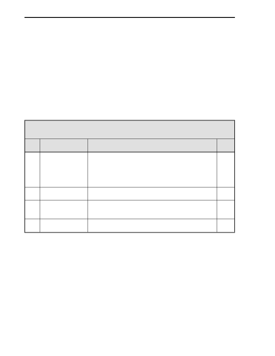
Table 4-2. Database Modules
Item
Title
Purpose
See
Table
1
Analog Input Module
This module is used to configure the voltage/current input
signals (e.g., 0-5 volts [0-20 mA], 1-5 volts [4-20 mA]) and
how the two input signals are interpreted (linear or square
root representation, with or without smoothing). It is also
used to configure the vertical axis range (zero and span) on
the display.
4-3
2
Analog Output
Module
The primary purpose of this module is to select and set the
0 - 20 mA or 4 -20 mA output signals for ANO0 and ANO1.
4-4
3
Display Module
This module is used to define the number of displays (six
maximum) and to set the display order presentation of the
operator displays.
4-5
4
System Module
This module is used to set the instrument tag name and the
display brightness.
4-6
53ML5100 Manual Loading Station
4-2