Table 4-3. analog input (ani) module – Micromod Micro-DCI: 53ML5100A LOADING STATION User Manual
Page 42
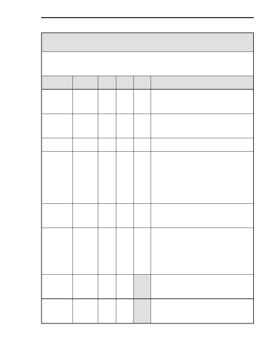
Table 4-3. Analog Input (ANI) Module
Purpose: This module is used to configure the voltage/current input signals (e.g., 0-5 volts
[0-20 mA], 1-5 volts [4-20 mA]) and how the input signals are interpreted (linear or square root
representation, with or without smoothing ). It is also used to configure the vertical axis range
(zero and span) on the display.
Title
Symbol
ANI
Data-
point
De-
fault
Attribute
Analog
Input
(Display
Only)
ANI0
ANI1
ANI0
ANI1
H000
H001
0
0
This is the value in engineering units of the
measured input after all signal conditioning
has been applied.
Engineering
Span
SPAN0
SPAN1
ANI0
ANI1
C256
C257
100
100
This determines the upper range the analog
input represents in engineering units. The
upper range value equals Engineering Zero
plus Engineering Span.
Engineering
Zero
ZERO0
ZERO1
ANI0
ANI1
C276
C277
0
0
This is the lower range value.
Digital Filter
Index
DFILT0
DFILT1
ANI0
ANI1
B269
B270
3
3
This controls a first order filter that is applied
to the input signal. The time constant is
entered as an index value as follows:
0 - No Smoothing (no effect)
1 - 0.05 s 6 - 3.1 s 11 - 102 s
2 - 0.1 s 7 - 6.3 s 12 - 205 s
3 - 0.3 s 8 - 12.7 s 13 - 410 s
4 - 0.7 s 9 - 25.5 s 14 - 819 s
5 - 1.5 s 10 - 51.1 s 15 - 1638 s
0 - 5 V Input
NOBIAS0
NOBIAS1
ANI0
ANI1
L416
L417
0
0
Setting this parameter to 1 indicates the input
range is from 0 - 5 volts (0 - 20 mA); 0
indicates the input range is from 1 - 5 volts (4 -
20 mA).
Square Root
Signal
SQRT0
SQRT1
ANI0
ANI1
L440
L441
0
0
When a 0, it indicates the analog input signal
should be interpreted linearly.
When 1, it indicates the analog input signal
should be interpreted as a square root
representation of the value.
When square root is selected, input signals
less than 1% (10% input range) force the input
to its zero value.
Calibrate
Zero
CIZ0
CIZ1
ANI0
ANI1
B263
B264
This is the calibration zero adjustment. This
parameter is factory set and should not
need adjustment under normal operation.
See Section 5.3 for calibration information.
Calibrate
Span
CIS0
CIS1
ANI0
ANI1
C296
C297
This is the calibration span adjustment. This
parameter is factory set and should not
need adjustment under normal operation.
See Section 5.3 for calibration information.
Section 4. Configuration Parameters
4-3