Table 3-3. procedure to alter a datapoint, Figure 3-10. entry line ten character field – Micromod Micro-DCI: 53ML5100A LOADING STATION User Manual
Page 32
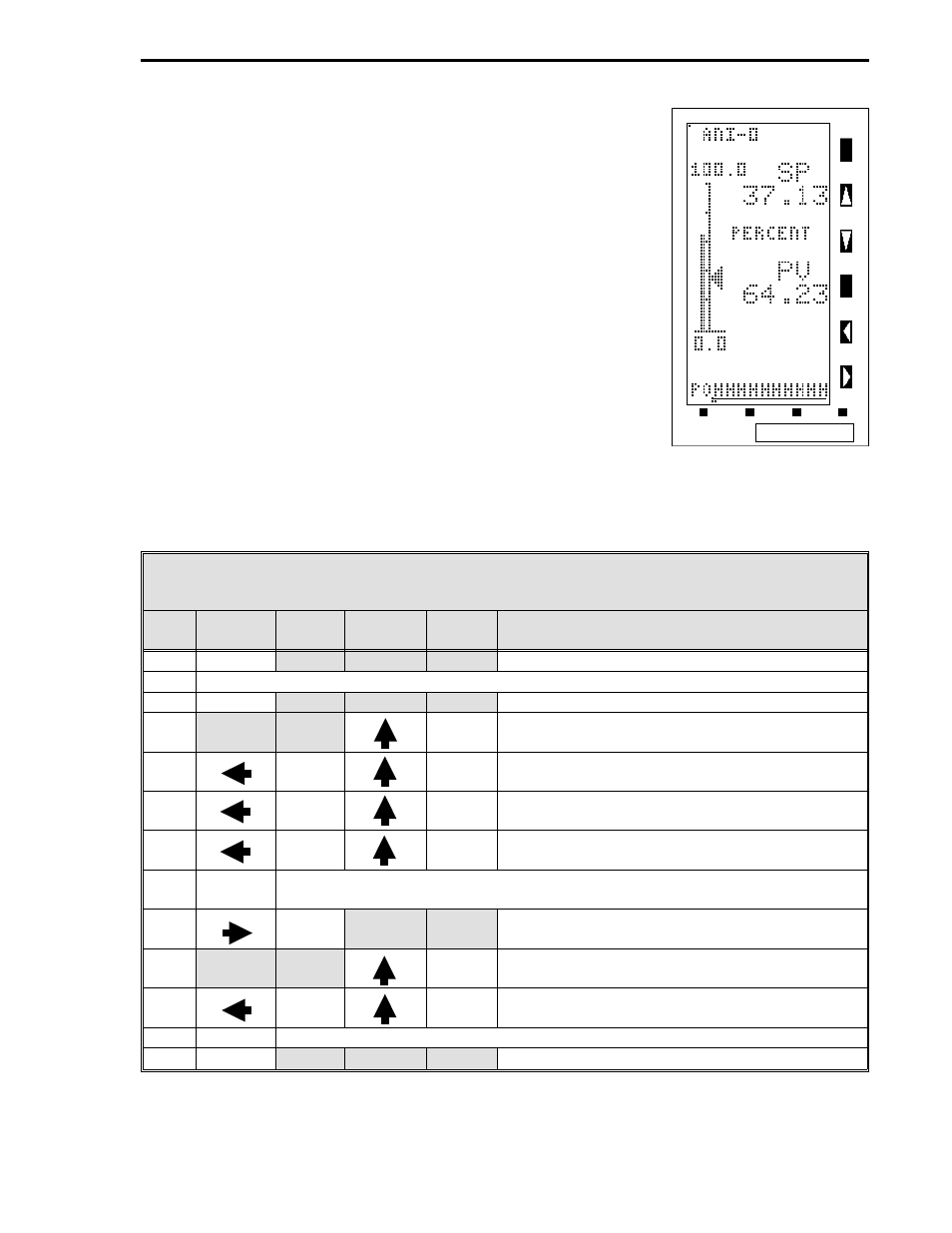
Table 3-3. Procedure to Alter a Datapoint
Step
Press
Once
Shift
Result
Press to
Locate
Target
Char.
Result
1
z
Puts instrument in engineering mode.
2
If CONFIGURE does not appear, press 2.
3
3
Displays entry line: POINT .
4
C
Puts C on entry line: POINT .C.
5
.C
∆
2
Shifts C and puts 2 on entry line:
POINT .C2.
6
.C2
∆
5
Shifts C2 and puts 5 on entry line:
POINT .C25.
7
.C25
∆
6
Shifts C25 and puts 6 on entry line:
POINT .C256.
8
3
Enters address to display datapoint contents. The address with the contents
are displayed as follows: C256 100.000.
9
hold
.
locator
C256 contents shifted right; only the locator point
remains on the entry line: C256 .
10
5
Puts 5 on entry line: C256 .5.
11
.5
∆
0
Shifts 5 and puts 0 on entry line:
C256 .50.
12
3
Enters the value 50 in datapoint C256.
13
z
Returns instrument to operator mode.
Note:
∆
= space.
3.3.3 ALTERING A DATAPOINT
The procedure in Table 3-3 illustrates how to alter the contents of data-
point C256, which is ANI0 Engineering Span, from 100 to 50. Figure 3-
10 is provided to show the maximum input character length for the
engineering mode edit line. The edit line can accept ten characters.
The full ten character field is used primarily for the A type datapoint
text strings (tag names). Reference Table 4-1 in Section 4 for informa-
tion about the datapoint types. Note that in Figure 3-10, the PO is resid-
ual from the prompt POINT and that the input character string has ten
Hs underlined in the figure to illustrate the data entry field.
Figure 3-10. Entry
Line Ten Character
Field
Section 3. Displays and Push Buttons
3-9