Table 4-5. display module – Micromod Micro-DCI: 53ML5100A LOADING STATION User Manual
Page 45
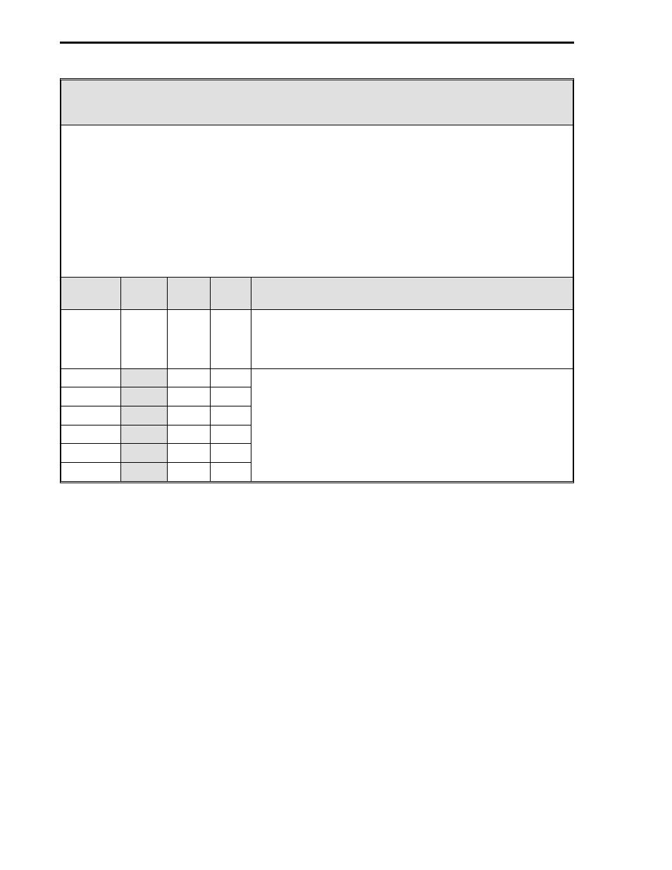
Table 4-5. Display Module
Purpose: This module is used to define the number of displays (six maximum) and to set the
display order presentation of the operator displays. The default settings are for six displays in the
order shown in Figure 1-1 and listed as follows:
1. Dual Channel Manual Loader (Chs. 1&2), 2. Single Channel Manual Loader (Ch. 1),
3. Manual Loader with Analog Input (Ch. 1), 4. Manual Loader with Analog Input (Ch. 2),
5. Analog Input Indicator with Setpoint Display (Ch. 1), and 6. Analog Input Indicator with
Setpoint Display (Ch. 2). Displays can be listed in any order and less than six can be specified,
for example, for a single channel configuration: B018 = 3 (three displays), B021 = 3, B022 = 5,
and B023 = 2. The displays will advance from display number 3, to display number 5, to display
number 2 each time the 2 push button is pressed. Pressing the 2 push button a fourth time
repeats the cycle with display 3 again.
Title
Symbol Data-
point
De-
fault
Attribute
Number
of
Displays
MDS
B018
6
It specifies the total number of operator displays that are
presented each time the 2 push button is pressed before the
cycle repeats itself beginning with the first display number
selected. The maximum number is 6.
Display 1
B021
1
Each datapoint is loaded with a display number from the list
above to set the display presentation order.
Display 2
B022
2
Display 3
B023
3
Display 4
B024
4
Display 5
B025
5
Display 6
B026
6
53ML5100 Manual Loading Station
4-6