Liquid Controls SP3850 User Manual
Page 38
SP3850 Flow Computer
34
ENTER
ENTER
ENTER
ENTER
ENTER
6.3.14 (Continued)
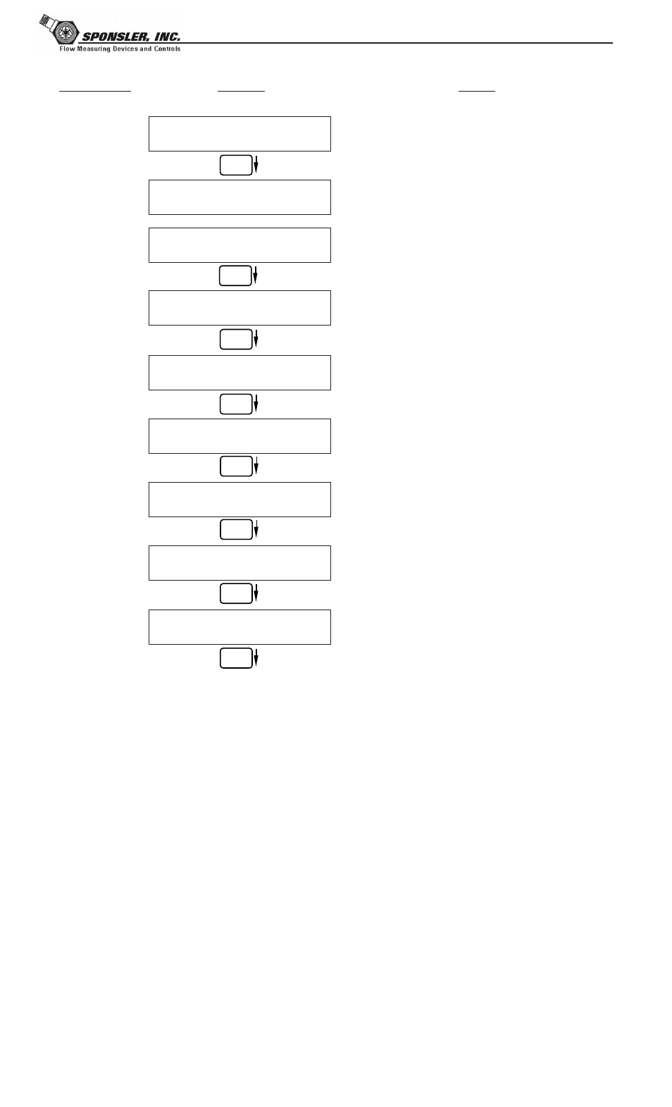
SETUP RELAYS
(Relay 3 & Relay 4)
ENTER
SETUP RELAYS
Rly1 Rly2
Rly3 Rly4
RELAY 3 USAGE
Rate Tot Aux Ovr NA
RELAY 4 USAGE
Rate Tot Aux Alrm NA
ASSIGN AUX CHANNEL
AUX 1 AUX 2
RELAY 3 DELAY sec
0
RELAY 3 MODE
LO_ALARM HI_ALARM
RELAY 3 DURATION
#####
RELAY 3 SETPOINT
####### gal
RELAY 3 HYSTERESIS
##### gal/m
Advance To
SETUP CONTROL INPUTS
Select the desired Relay for setup.
(Relays 3 & 4 Optional)
If Relay 3 Selected,
Choose Rate, Total, Aux, Ovr or NA.
If Relay 4 Selected,
Choose Rate, Total, Aux, Alrm or NA.
If Aux selected, enter desired auxilliary
channel.
If Rate / Aux selected, enter desired relay
activation delay value.
Select the desired Relay Activation for Rate/Aux.
Low: Relay activates when reading is below
setpoint.
High:Relay activates when reading is above
setpoint.
If Total Selected, Enter desired Relay
Duration.
Enter the desired Setpoint.
If Rate, selected, Enter desired Relay
Hysteresis.
NOTE:
Settings for Relays
3 & 4 may be
entered even if
relays are not
supplied. The
settings will still
trigger display
alarms.
Sub-menus
Display
Notes
ENTER
RELAY NOTES & CONSIDERATIONS
1. Relay activation is based on the computed readings not the displayed value. Therefore the display
damping factor will not affect the relay response time. The RELAY DELAY feature allows the user
to enter a time delay for relay activation. This feature is very useful in applications where short over/
under range conditions are not considered alarm conditions.
2. When INSTRUMENT TYPE is set to batcher, Relay 1 is reserved for PRESET and Relay 2 is
reserved for PREWARN.
3. Setting the relays to NA (Not Assigned), will allow the relay activation to be controlled via the RS-
232 Serial and/or RS-485 Modbus ports.
4. Relay 3 and Relay 4 settings may be used to trigger display alarm conditions even if the relays are
not supplied.
ENTER