Smart touch controller inputs – Controlled Products Systems Group HRG 220-A ST User Manual
Page 39
Installation and Maintenance Manual
25
Wiring Control Inputs to the Smart Touch Controller
1. Test the basic open and close operator function before wiring the external control inputs. This
makes it easier to troubleshoot if an unexpected function issue arises.
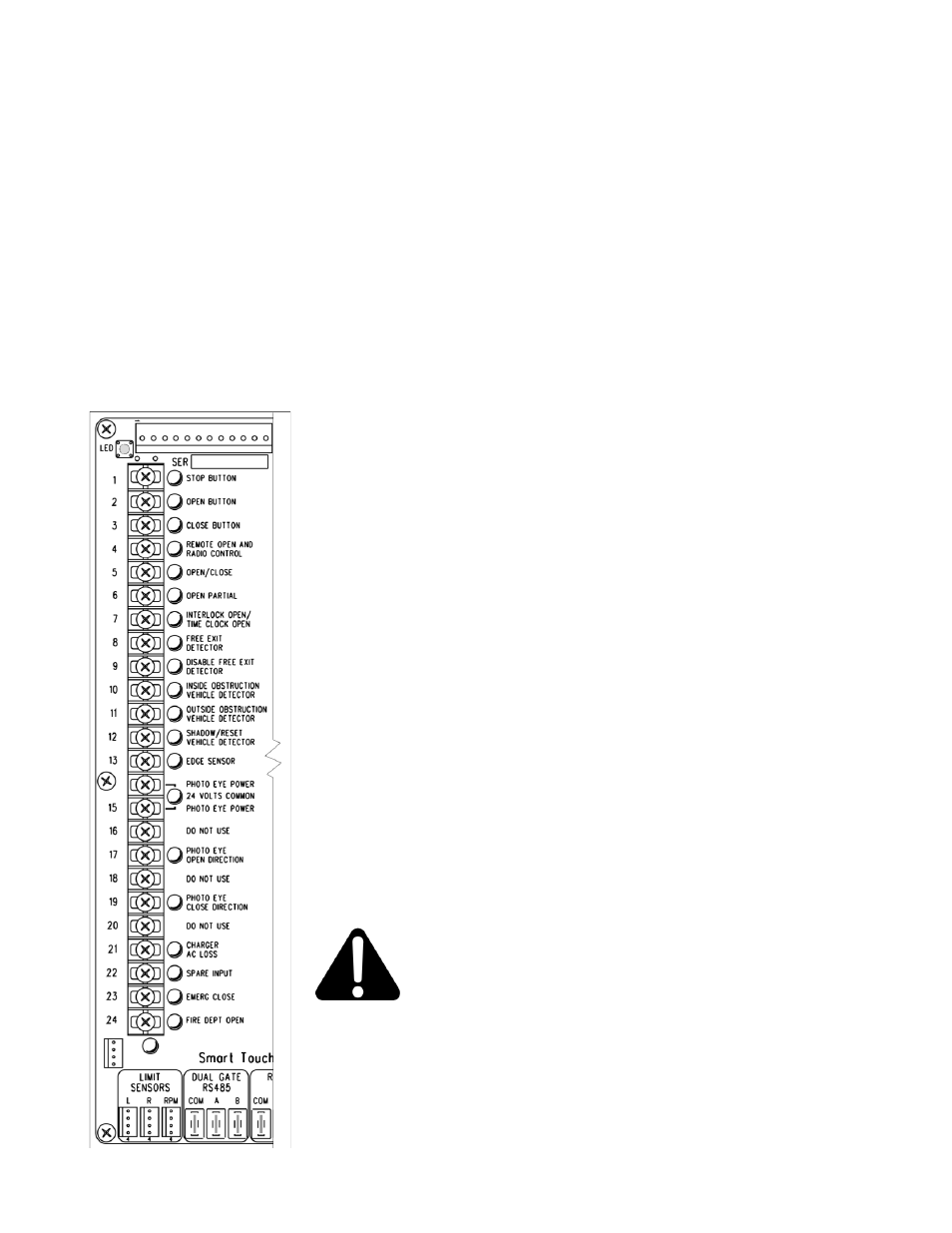
2. Each input has an LED to indicate when that input is active.
a. On Classic ST Controllers, to disclose the input status, the LED button must be pushed and held.
This button is in upper left corner near the Stop input.
b. On New Generation ST Controllers the LED’s are active as long as long as the AC power is
applied. On DC units, if the AC power to the charger is off, the LED button will need to be pushed
to illuminate the LED. The button is in the lower left beneath the terminal strip.
3. All the control device inputs listed below are shown as a single input because the other wire is
connected the Common Terminal Buss on the Power Supply board. The Emergency Close and
Fire Dept. Open inputs are an exception and require a +24 Volt input in order to be activated.
The +24 is available at the spade terminals next to the Common Buss.
Smart Touch Controller Inputs
1) *Stop Push button (N.C. input, jumper to Common if unused)
2) *Open Push Button (not for radio or remote access controls)
3) *Close Push button (not for radio or remote access controls)
4) Remote Open & Radio Control (For radio / remote open device -
menu opt. to also close)
5) Open/Close button (pushbutton or radio controls)
6) Partial Open (this input disabled on swing gates)
7) Open interlock input or Time clock Open (menu configurable)
8) Free Exit vehicle detector
9) Disable Free Exit vehicle detector/Timer to Close
(Free Exit is only disabled when Close Limit Switch tripped)
10) Inside Obstruction vehicle detector (Inside reversing loop)
11) Outside Obstruction vehicle detector (Outside reversing loop)
12) Shadow vehicle detector (This is the loop under the arc of the gate)
13) Edge Sensor (one input works for both directions of travel)
(14-15) Photo eye Common Power (supply for PE power & PE Com)
(17) Photo eye Open direction (beam spans the area where gate opens)
(19) Photo eye Close direction (beam spans across the road)
(21) Charger AC power loss (only used in battery type operators)
(22) Gate Lock Interlock Input (Software
≥ h3.25,-Prevents start until
external gate lock releases)
Classic Board = Spare Input (Software
trigger) Overrides photo eyes, gate edge & vehicle detectors.
(24) **Fire Dept. Open (must menu enable and input +24 Volts to trigger)
Overrides photo eyes & gate edge.
* Do not connect an external control to terminals #1, 2 or 3,
unless the controls are located such that there is a clear view
of the entire gate area. For controls not within sight, use input
terminals #4, 5, 6 or 7.
**The Emergency Close and Fire Dept. Open inputs are to be
used only if access to these controls is guarded in sufficient manner such that
there is always supervision when activated.
Attention
Attention