Controlled Products Systems Group HRG 220-A ST User Manual
Page 31
Installation and Maintenance Manual
17
Detailed Installation Instructions for HRG Swing Gate Operator
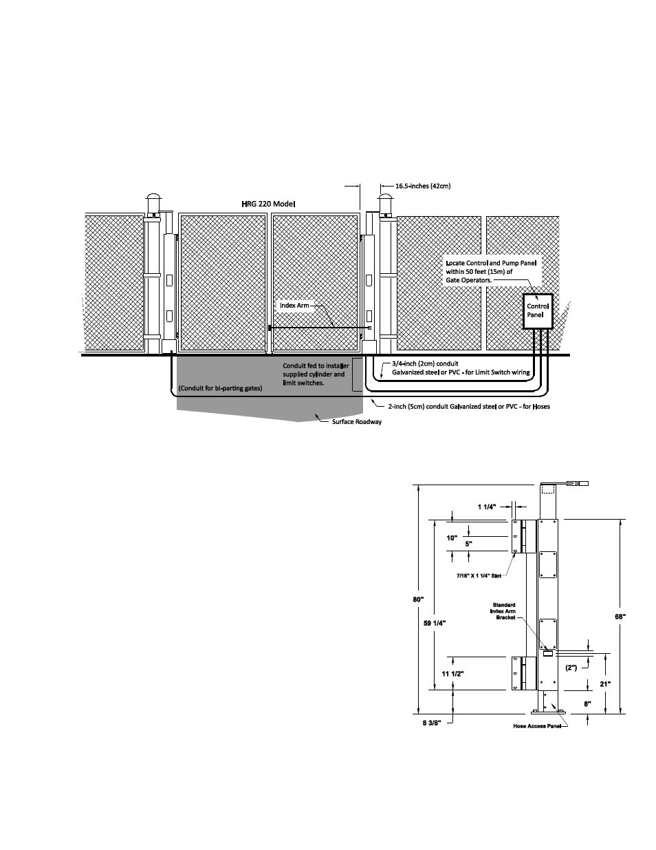
1) Mount control box and connect all conduit fittings.
a) Mount controller box within 100ft (30m) of the gate operator, preferably within 20ft (6m). If
installing the DC version of the operator, mount the battery power supply very near the controller
enclosure because of the high current demand by the DC motor
– See the Two Part operator
section.
b) Attach all electrical conduits as required, note the diagram below and see step number 3.
2) Mount operator post
a) Using four
⅝-inch to ¾-inch anchor bolts, mount
the 12-inch square operator base with 1-inch
clearance between the base and the backing post
or wall. The gap between the operator post and
the backing post will be 3½-inches. It is important
that the finished installation be plumb and true.
Use shims if necessary to level the operator base.
b) Attach the top of the operator to the backing post
or supporting wall, using the bracket provided.
The attaching bracket "sleeves" inside the top of
the operator post. See page 11 for Top Cap
Options.
NOTE: The backing post/column, (provided by
others) must accommodate all of the "tip over"
loads imposed by the gate panel.