Controlled Products Systems Group HRG 220-A ST User Manual
Page 21
Installation and Maintenance Manual
7
Putting it all together: sample plans
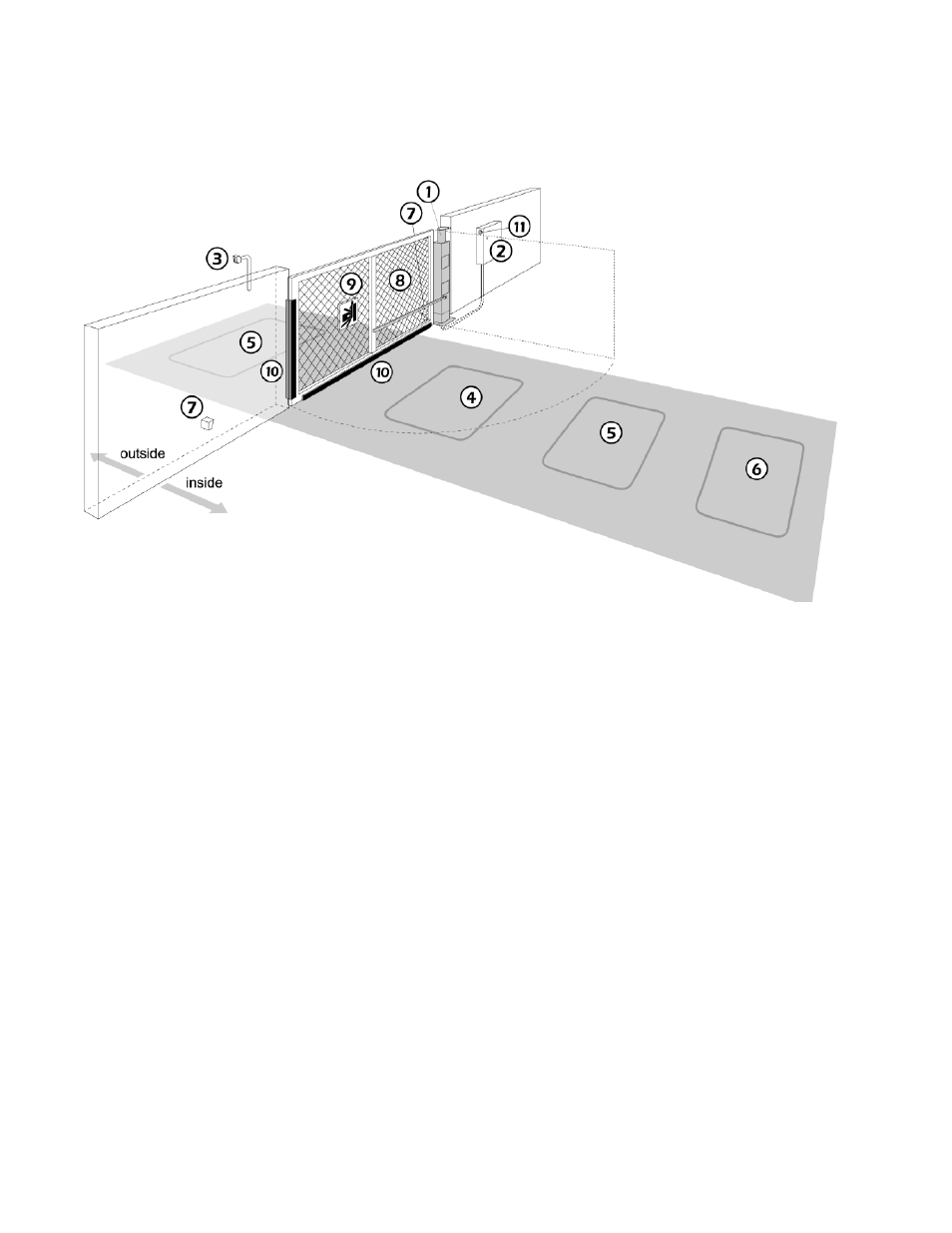
Fig. D A swing gate that opens to empty space
This figure illustrates a sample plan for a gate, incorporating the elements described below.
1. The swing gate operator automates the gate. It may be ordered for left hand or right hand as shown.
2. The weather resistant NEMA 3R controller box houses the Smart Touch control and hydraulic pump.
3. An entrance control opens the gate for entry.
4. Shadow loop prevents the gate from closing on a car. This loop is active only when the gate is fully
opened or fully closed.
5. Obstruction loops (Located inside and outside the swing arc of the gate)
6. Optional free exit loop
7. Photo eyes stop the gate to help prevent vehicular or personal entrapment.
8. Safety mesh on the gate panel prevents reaching through the gate panel.
9. Warning signs alert users to the danger of entrapment when using automatic gate operators.
10. Sensing edges on the bottom of the gate and inside and the outside leading edge of the gate panel
send a signal to operator to stop and reverse when an obstruction is encountered.
11. A warning buzzer sounds an alert when an obstruction is sensed and can warn before gate motion.