Controlled Products Systems Group HRG 220-A ST User Manual
Page 33
Installation and Maintenance Manual
19
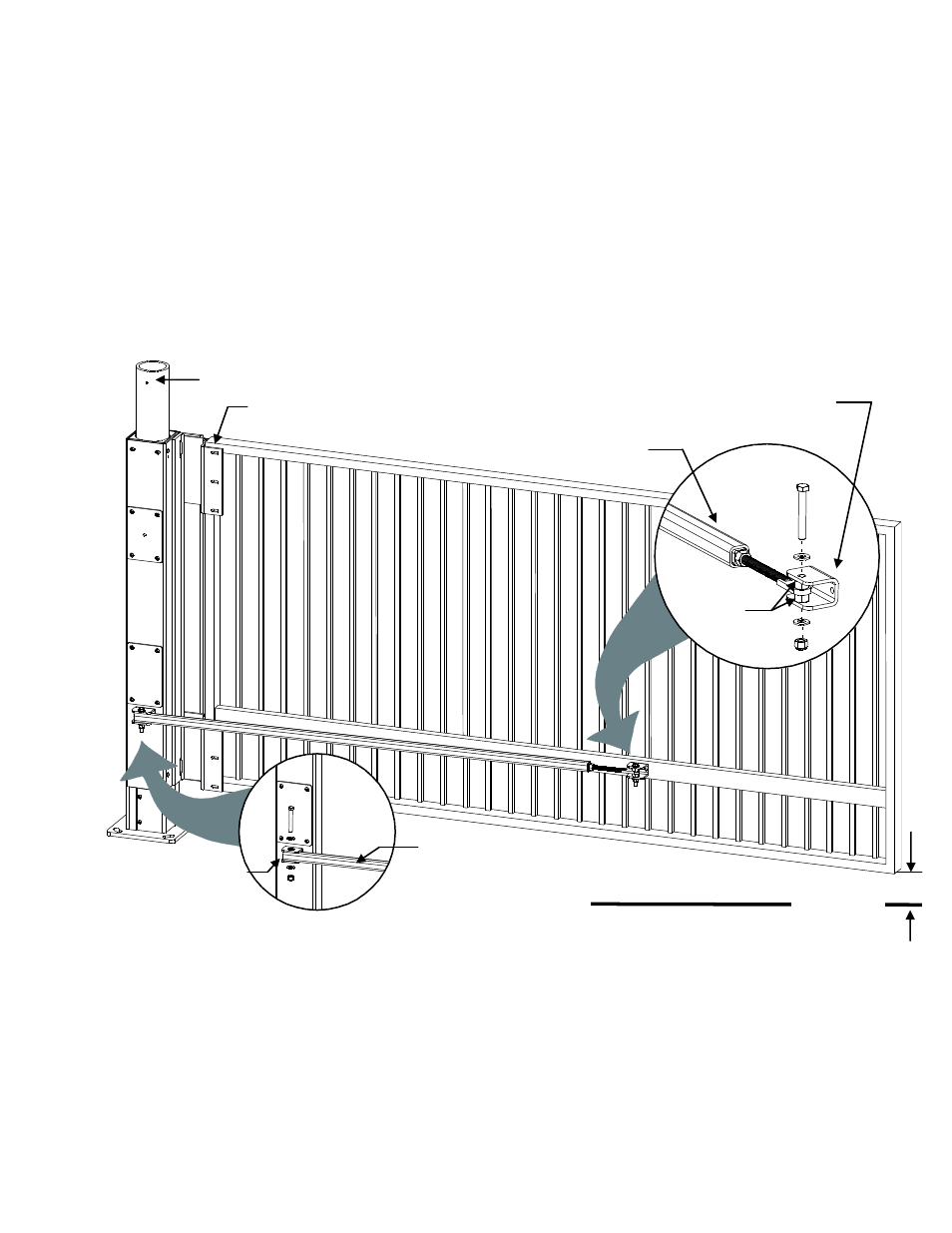
Mounting the Gate Panel, Index Arm, and Lock Pin Assembly
1) Mount the gate panel with six 3/8-inch bolts through both sides of the 11-inch hinge. Be sure to
provide the correct clearance between the gate and the road surface. See the illustration on page 9.
Allow 3-inches of clearance at the far end of the gate panel. See illustration below.
2) Measure and mark where the index arm bracket will be situated along the lower horizontal member of
the gate. (The best attachment point is about one-third to one-half of the gate length from the gate
hinge.) Clamp the bracket to the gate panel.
3) Screw the eye-bolt into the threaded end of the index arm tube. A minimum of 3-inches of thread
should be encased inside the tube.
4) Align the eye bolt with the index arm bracket and drop the bolt through both the bracket and eye bolt,
temporarily fastening the eye bolt to the gate bracket.
5) Make sure the gate is closed. Extend the tube into the bracket on the Support Post. See the
illustration above.
6) Measure the tube and mark where it will be cut.
7) Cut the index arm and drill a ½" hole in the tube where it attaches to the Support Post Bracket.
8) Use the fasteners provided to secure it to the Support Post Bracket. See illustrations.
9) Cycle the gate to check that the index arm is positioned properly, and then securely fasten the
threaded-end of the index arm to its mounting bracket on the gate panel as shown in the illustration.
The 5/8-inch nuts are used as spacers.
Support Post Bracket
Insert fasteners to
secure index arm.
Mount gate to hinge with 3/8-inch
bolts (not provided)
Bracket – fasten to gate (weld or
bolt). Insert fasteners and spacers
to secure index arm to gate.
Index arm
5/8-inch
nuts used
as spacers
Index arm
Support Post
Grade level
3"