Lock pin assembly – Controlled Products Systems Group HRG 220-A ST User Manual
Page 34
Installation and Maintenance Manual
20
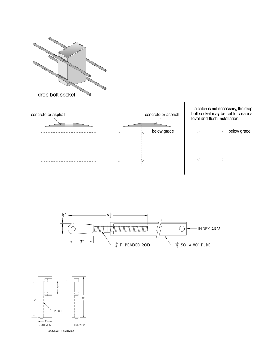
10) Mount the locking pin mechanism on the lower corner of the free end of the gate panel in such a
position that the pin penetrates 2 inches into its lock receptacle when the gate is fully closed.
11) Bury the receptacle tube in the roadway so it acts as
a socket for the locking pin. If the locking pin
assembly provided by HySecurity is not used, the
tube should have an angular cut on the tip and project
about two inches above the grade to act as a "catch"
for the locking pin. Use a 3½" x 1½
‖ tube of
appropriate length for this purpose. Use blacktop or
grout to create a mound around the exposed tube, so
passing vehicles encounter a smooth bump.
12) Adjust the threaded end of the index arm so as the free end of the gate closes, the locking pin strikes
and slides down into the receptacle. Set the index arm adjustment so the gate swings slightly past
center and the locking pin strikes the back of the receptacle. Tighten all parts of the index arm
assembly firmly (100 ft-lbs) for trouble free operation.
Lock Pin Assembly
CAUTION: If the locking pin mechanism is not used, security of
this system is adversely affected and the operator drive shaft
may be exposed to high stresses by wind loading or vandals. If
the lock pin receptacle is not built or installed to create a strike
stop for the gate, the lock pin may not always align with the
receptacle.
NOTICE: If the locking pin mechanism is not used, security of
this system is adversely affected and the operator drive shaft
may be exposed to high stresses by wind loading or vandals. If
the lock pin receptacle is not built or installed to create a strike
stop for the gate, the lock pin may not always align with the
receptacle.
2”