1 crank arm assembly, 4 arm assembly and installation – Controlled Products Systems Group 6300-080 User Manual
Page 22
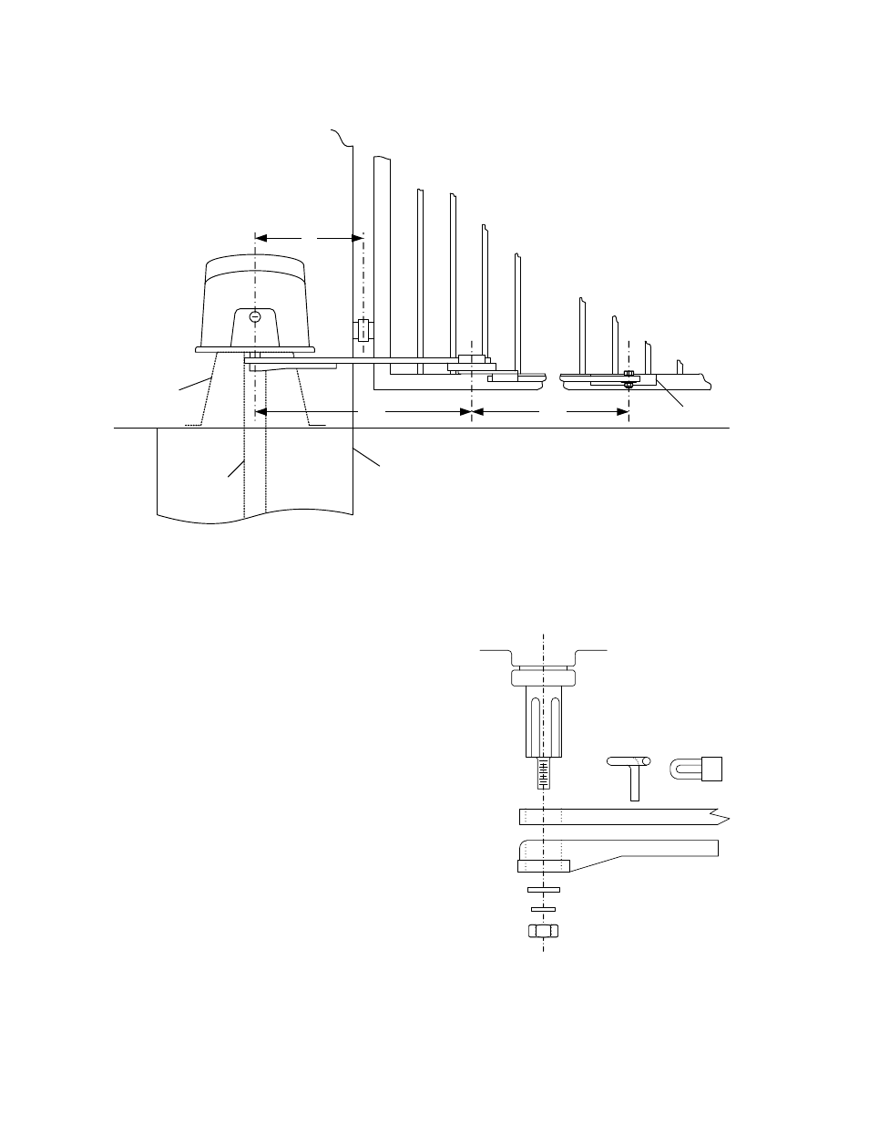
1.4 Arm Assembly and Installation
Hinge
Mounting
Pad
Post
Mount
Pad
Mount
24
12
37.5
Gate
Bracket
Figure 10
1.4.1 Crank Arm Assembly
Main Shaft
Crank Arm
Crank Power Arm
Washer 1 7/8 OD x 1/2 ID x 1/8
1/2 SAE Washer
1/2-13 Nut
Lock
Lock Pin
1. Attach the crank arm and crank power arm
to the operator output shaft using the
supplied hardware (Figure 11). Position
the arm so that it is pointing towards the
gate.
2. Do not insert the lock pin or lock into the
crank arm assembly at this time. It will be
installed later.
3. Adjust the lock nut so that it is snug
against the washer, but will still allow the
crank power arm to turn with little force.
Figure 11
Page
22
6300-065-E-4-08