1 post mount, 2 mounting post/base plate installation – Controlled Products Systems Group 6300-080 User Manual
Page 16
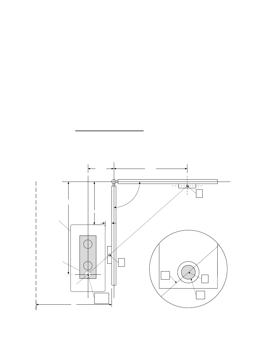
1.2 Mounting Post/Base Plate Installation
1.2.1 Post
Mount
1.
Screw the two mounting posts supplied into the operator mounting plate.
2.
Using the dimensions shown below, locate the mounting plate/post assembly as
shown.
3.
Note that when the mounting plate/post assembly is properly located, the operator
output shaft (Point C) will intersect an imaginary line drawn from the gate mounting
bracket in the closed position (A1) to the gate mounting bracket in the open position
(A2).
4.
Once the location of the mounting plate/post assembly has been determined,
construct a form for the concrete pad according to Figure 3 and place the assembly
into the form. Note that the depth of the pad is determined by soil conditions and
local building codes.
5.
Determine the height of the assembly required for your installation. Refer to Figure 4.
6.
IMPORTANT!! Prior to pouring concrete to anchor the mounting plate/post
assembly, be sure that POINT C is located correctly and that the mounting
plate is level and at the correct height.
Conduits can be run into the pad as
required.
7.
Let the concrete cure for 48 hours before proceeding with the installation of the gate
operator.
12.00
34.00
43.00
90.0°
Post Mount Mounting
Bracket
Operator
Housing
A1
A2
Detail A
A1 – A2
Line
Output
Shaft
20.00
3.00
35.00
Minimum side room required for shown mounting position.
Point
C
C
See Detail A
Figure 2
Page
16
6300-065-E-4-08