In-line installation 2822 submersible installation, 2823 submersible installation maintenance – GF Signet 2819-2823 Conductivity-Resistivity Electrodes User Manual
Page 4
Optional
submersion
fitting kit
#3-2820.390
1
2
1-1/4 turns
past finger
tight
3/4 in. NPT
Customer supplied
pipe
Customer supplied
coupling
Sealant
Sealant
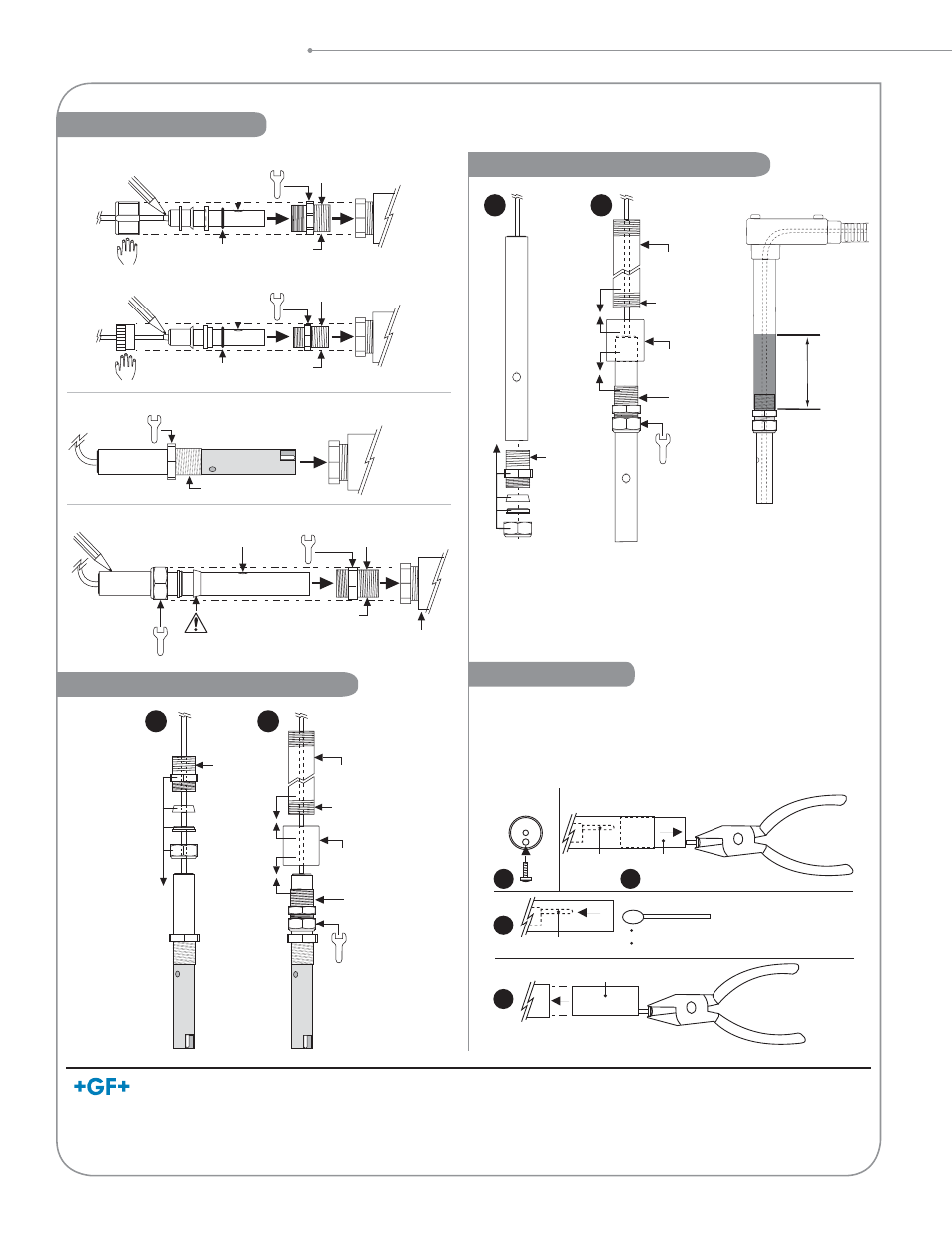
Installation and Maintenance
In-Line Installation
2822 Submersible Installation
1
2
1-1/4 turns
past finger
tight
3/4 in. NPT
Customer supplied
coupling
Customer supplied
pipe
Sealant
Sealant
Fill with
3 in. to 4 in.
of sealant
• Attach ¾ in. watertight pipe to the top of the sensor.
• Secure the threaded connection to prevent any leakage.
• For additional defense against possible accumulation of
condensation at the back seal area of the sensor, fi ll the lower
75 mm to 100 mm (3 in. to 4 in.) of conduit or extension pipe with
a fl exible sealant such as silicone.
2823 Submersible Installation
Maintenance
2818/2819/2820/2821
Customer
supplied
pipe tee/
reducer
Standard
fitting kit
Mark hole
position
3/4 in. NPT
Hand
tighten only!
O-ring
Sealant
Hole up
2822
Customer
supplied
pipe tee/
reducer
Sealant
2823
1-1/4 turns
past finger tight
Hole up
Mark hole position
Install behind
hole ONLY!
Customer supplied
pipe tee/reducer
3/4 in. NPT
Sealant
A
Sensor tip
(side view)
Electrode
B
Insulator
C
Electrode
Cotton swab
Clean electrode
Clean metal body
8-32
Sensor tip
(end view)
D
Insulator
Sensor tip
(side view)
2823-1 Sensor Tip Removal Procedure:
• Any coatings on electrodes will cause readings to drift or show
poor response.
• Clean metallic surfaces with a mild detergent and a non-abrasive
brush or cotton swab.
Hand
tighten only!
O-ring
Sealant
Hole up
Mark hole
position
Customer
supplied
pipe tee/
reducer
1/2 in. NPT
3-2820.392
Optional
fitting kit
Georg Fischer Signet LLC, 3401 Aero Jet Avenue, El Monte, CA 91731-2882 U.S.A. • Tel. (626) 571-2770 • Fax (626) 573-2057
For Worldwide Sales and Service, visit our website: www.gfsignet.com • Or call (in the U.S.): (800) 854-4090
For the most up-to-date information, please refer to our website at www.gfsignet.com
3-2820.090-1 Rev N 10/13 English
© Georg Fischer Signet LLC 2013
*Installation tip: Mark the sensor body to indicate the position of the vent hole. During installation,
align the vent hole mark so it faces upward or against the process fl ow to prevent air bubble entrapment.