Wiring processpro propoint, Integral installation detail, Smartpro – GF Signet 2839-2842 NPT Conductivity-Resistivity Electrodes User Manual
Page 3: Via 2850 sensor electronics
3
2839-2842 Conductivity Sensors
Sensr Gnd
(SHIELD)
Iso. Gnd
(BLACK)
Temp. IN
(WHITE)
Signal IN
(RED)
10
9
8
7
To 8850-1
To 8850-2 and 8850-3
Sensr Gnd
(SHIELD)
Iso. Gnd
(BLACK)
Temp. IN
(WHITE)
Signal IN
(RED)
14
13
12
11
To 5800CR
RED
WHITE
BLACK
SILVER (SHLD)
S
hld
Signal IN
Temp. IN
Iso. Gn
d
To 8860
SHLD
ISO GND
TEMP 1
SGNL 1
RED
WHITE
BLACK
SHIELD (Gnd)
SHLD
ISO GND
TEMP 1
SGNL 1
RED
WHITE
BLACK
SHIELD (Gnd)
Ch
1
Ch
2
Sensr Gnd
(SHIELD)
Iso. Gnd
(BLACK)
Temp. IN
(WHITE)
Signal IN
(RED)
10
9
8
7
To 8850-1
To 8850-2 and 8850-3
Sensr Gnd
(SHIELD)
Iso. Gnd
(BLACK)
Temp. IN
(WHITE)
Signal IN
(RED)
14
13
12
11
To 5800CR
RED
WHITE
BLACK
SILVER (SHLD)
S
hld
Signal IN
Temp. IN
Iso. Gn
d
To 8860
SHLD
ISO GND
TEMP 1
SGNL 1
RED
WHITE
BLACK
SHIELD (Gnd)
SHLD
ISO GND
TEMP 1
SGNL 1
RED
WHITE
BLACK
SHIELD (Gnd)
Ch
1
Ch
2
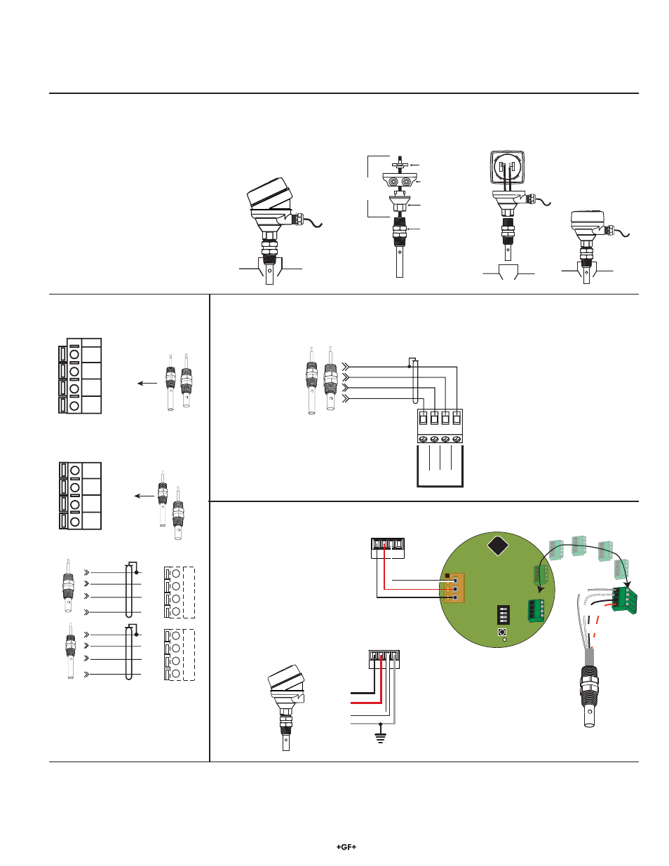
4. Wiring
ProcessPro
ProPoint
• Do not route electrode cable in conduit containing AC power wiring. Electrical noise may interfere with electrode signal.
• Routing electrode cable in grounded metal conduit will help prevent electrical noise and mechanical damage.
• Seal cable entry points to prevent moisture damage.
• For resistivity measurements above 10 MΩ or below 20 °C, maximum cable length is 7.6 m (25 ft).
8850
Conductivity Transmitter
locking ring
conduit base
8052
integral
adapter
electrode
Max cable length
15.2 cm (6 in.)
9900
with 8052 Integral Mounting Kit
and 9900.396 Angle Adjustment Adapter
Integral installation detail
• 3-8052 Integral Kit and 3-9000.392-X Liquid Tight Connector kit are required. (See Parts and Accessories on back page).
• Cut the cable to approx. 15 cm (6 in.).
• Strip outer cable cover back 5 cm (2 in.).
• Strip each conductor to expose 1 cm (3/8 in.) of bare wire.
• Tin each conductor with solder for best results.
V+ DAT
A
GND SHLD
(shown with
8052 Integral Mounting Kit
and 9900.396 Angle Adjustment Adapter)
Black
Red
Shield
White
9900 S
3
L
Input Connector
Sensr Gnd
(SHIELD)
Iso. Gnd
(BLACK)
Temp. IN
(WHITE)
Signal IN
(RED)
10
9
8
7
To 8850-1
To 8850-2 and 8850-3
Sensr Gnd
(SHIELD)
Iso. Gnd
(BLACK)
Temp. IN
(WHITE)
Signal IN
(RED)
14
13
12
11
To 5800CR
RED
WHITE
BLACK
SILVER (SHLD)
S
hld
Signal IN
Temp. IN
Iso. Gn
d
To 8860
SHLD
ISO GND
TEMP 1
SGNL 1
RED
WHITE
BLACK
SHIELD (Gnd)
SHLD
ISO GND
TEMP 1
SGNL 1
RED
WHITE
BLACK
SHIELD (Gnd)
Ch
1
Ch
2
SmartPro
SW1
D3
1
2
3
1
2
3
4
ON
CTS
V+
D
AT
A
GND
SHLD
V+
Gnd
Data
Temp. IN
(WHITE)
Sensr Gnd
(SHIELD)
Signal IN
(RED)
Signal RTN
(BLK)
Black
Red
White
9900 S
3
L Input
8850
Conductivity Transmitter
locking ring
conduit base
8052
integral
adapter
electrode
Max cable length
15.2 cm (6 in.)
9900
with 8052 Integral Mounting Kit
and 9900.396 Angle Adjustment Adapter
via 2850 Sensor Electronics