Installation, Cell constant selection – GF Signet 2839-2842 NPT Conductivity-Resistivity Electrodes User Manual
Page 2
2
2839-2842 Conductivity Sensors
3. Installation
Fill with
3 to 4 in.
of sealant
Appliquer un
élastomère
par 7-10 cm
Füllen Sie
mit 7 bis 10 cm
Dichtungsmittel
Llene con
3 a 4 pulg.
de sellante
• Inspect threads to ensure integrity. Do not install an electrode with damaged threads.
• Apply sealant or PTFE tape to threads.
• Wetted materials include 316L stainless steel, PEEK and FPM (FPM O-ring inside 2841, 2842). Check for chemical compatibility
before installing electrode.
• Electrodes are supplied with 4.6 m (15 ft) of cable. It may be extended to a maximum 30 m (100 ft).
• For resistivity measurements above 10 MΩ or below 20 °C, maximum cable length is 7.6 m (25 ft).
• When using the 5800CR, 5900, 8850 and 8860 transmitters, maximum cable length is 4.6 m (15 ft).
• When using 9900, maximum cable length is 30.5 m (100 ft).
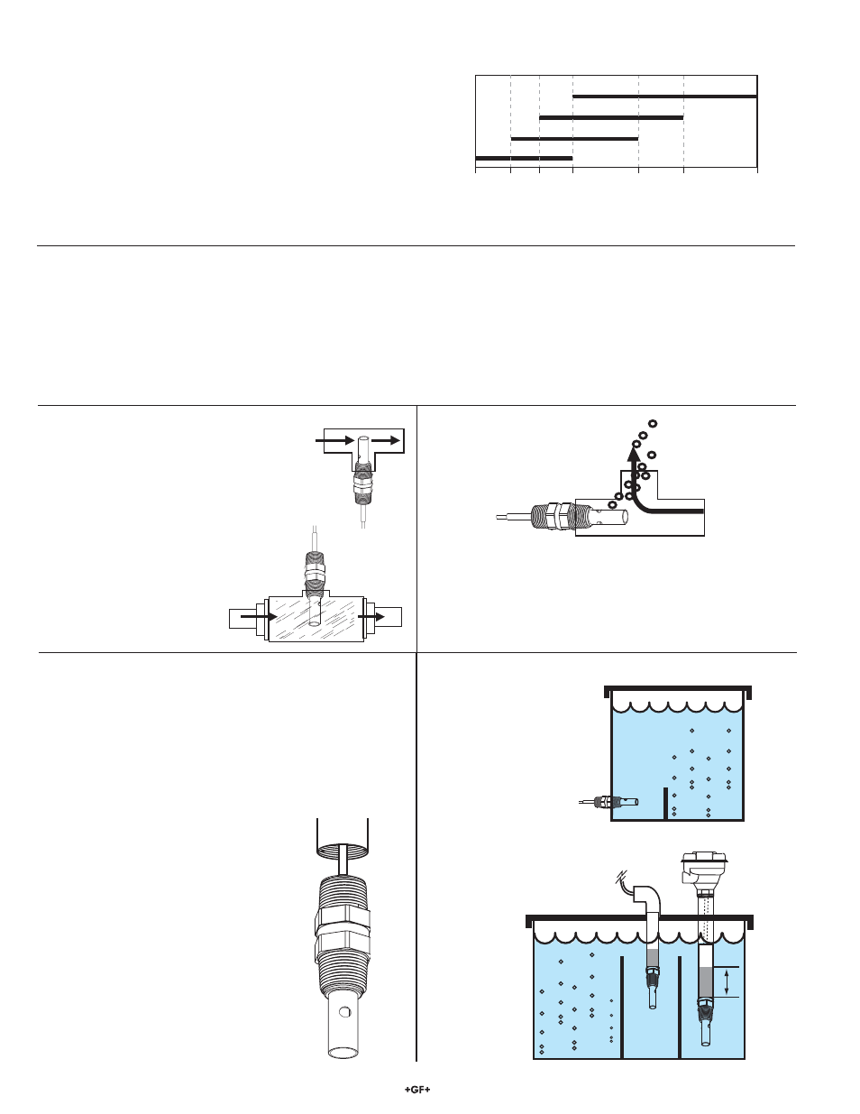
If the electrode is mounted vertically in
a tee, do not recess the openings inside
the tee. Mounting upside down may help
prevent air entrapment.
An oversized tee may also be helpful for
inline installations.
At least 4 threads (ANSI B1.20.1) must
be engaged to provide pressure capacity
per published specifications.
The preferred installation for in-line applications
directs flow straight into the electrode. This
configuration dislodges entrapped air bubbles,
and provides the best continuous sampling of the
fluid content.
3.2 Submersible installation
3
/
4
in. NPT or
ISO 7/1-R
3
/
4
In aerated vessels install the electrode
in a stillwell to prevent air from being
trapped inside the electrode.
Fill with
3 to 4 in.
of sealant
The nominal process value should be near the center of the range.
Ranges below are for use with Signet Conductivity Instruments:
• 2839 (0.01 cm
-1
): 0.010 to 100 µS (10 kΩ to 100 MΩ)
• 2840 (0.1 cm
-1
): 1 to 1000 µS (1 MΩ to 1 kΩ)
• 2841 (1.0 cm
-1
): 10 to 10,000 µS
• 2842 (10.0 cm
-1
): 100 to 200,000 µS
1. Feed cable into watertight conduit.
2. Apply thread sealant to the electrode before threading
conduit onto electrode. Avoid twisting the cable.
3. Secure cable with conduit or cable gland.
4. For additional defense against possible accumulation of
condensation at the back seal area of the electrode, fill the
lower 75-100 mm (3-4 in.) of conduit or extension pipe with a
flexible sealant such as silicone.
2. Cell Constant Selection
(100 MΩ)
(10 kΩ)
2839 0.01 cm
-1
2841 1.0 cm
-1
2842 10.0 cm
-1
2840 0.1 cm
-1
0.010µs 1µs 10µs 100µs
1000µs 10,000µs
200,000µs
Conductivity Range (µS)
Signet Conductivity/Resistivity Electrode Ranges
Electrode Models
Custom cell certificate
The sensor was delivered from the factory with a calibration
certificate. The information provided on the certificate (custom
cell constant and temperature offset) should be entered in the
transmitter/controller. See individual product manual for details.
3.1 In-Line Installation