GF Signet 525 Metalex Flow Sensor User Manual
Page 3
3
Signet 525 Metalex Flow Sensor
8. Maintenance
The 525 sensor requires little or no maintenance of any kind, with the exception of an occasional sensor/paddlewheel cleaning.
7. Sensor Removal Procedure
1. Depressurize and drain pipe.
2. Remove the four sensor fl ange bolts and lock washers. Pull
upward on the sensor fl ange with an alternating twisting
motion.
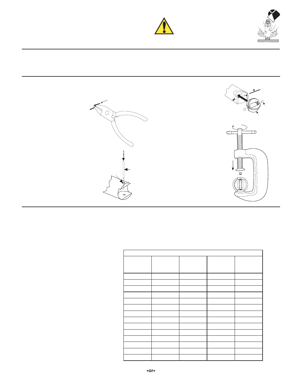
9. Rotor Replacement Procedure
1. With a small pair of needle-
nose pliers, fi rmly grip the
center of the rotor pin (axle)
and with a twisting motion,
bend the rotor pin into an
"S" shape. This should pull
the ends of the pin out of the
retainers and free the rotor
assembly.
Rotor Pin
Existing
Retainer
New
Bearings
Rotor
Assembly
Punch
Retainer
Rotor Pin
10. K-Factors
The K-Factor is the number of pulses the sensor will generate for each engineering unit of fl uid which passes. They are listed in U.S.
gallons and in liters. For example, in a 1 inch SCH 40S stainless steel pipe, the sensor generates 266.17 pulses per gallon of fl uid
passing the rotor. K-Factors are listed for SCH 40S stainless steel pipes up to 12 inch.
Conversion Formulas
1 U.S. gallon =
0.003785 cubic meters
0.000003069
Acre
feet
8.3454 pounds of water
SCH 40S STAINLESS STEEL PIPE PER ANSI B36.19
PIPE
SIZE
K-FACTOR
PULSES/
U.S. GAL
K-FACTOR
PULSES/
U.S. LITER
A-FACTOR
GPM/Hz
A-FACTOR
LPM/Hz
1/2 IN.
873.03
230.66
0.0687
0.2601
3/4 IN.
515.41
136.17
0.1164
0.4406
1 IN.
266.17
70.322
0.2254
0.8532
1 1/4 IN.
148.84
39.324
0.4031
1.5258
1 1/2 IN.
107.98
28.528
0.5557
2.1032
2 IN.
64.808
17.122
0.9258
3.5042
2 1/2 IN.
44.685
11.806
1.3427
5.0822
3 IN.
28.579
7.5506
2.0994
7.9464
4 IN.
16.302
4.3070
3.6805
13.931
5 IN.
10.237
2.7046
5.8611
22.184
6 IN.
7.0057
1.8509
8.5645
32.416
8 IN.
3.9641
1.0473
15.136
57.289
10 IN.
2.4690
0.6523
24.301
91.981
12 IN.
1.6894
0.4463
35.516
134.43
WARNING!
Do not remove from pressurized lines.
Wear safety goggles and faceshield
during installation/service.
2. Remove rotor pin retainer from
each side by gently tapping it
inwards using a punch. Install a
new retainer into the sensor body
with its rotor pin clearance hole
inward. Only install one retainer at
this time.
3. Insert the new rotor assembly
and bearings into the rotor
housing of the sensor and
place the new rotor pin (axle)
through the open end of
the rotor housing, through
the rotor and bearings, and
into the previously installed
retainer.
4. Using a vise or C-clamp, press
the second retainer into the hole
in the sensor body while lining
up the rotor pin with the center
of the retainer hole.
NOTE
: A hammer and center punch
can also be used if a clamp or vice
is not available