GF Signet 525 Metalex Flow Sensor User Manual
Page 2
2
Signet 525 Metalex Flow Sensor
Signet Metalex Saddle Fittings (Sensor PN P525-3/-3S)
Pipe (in.)
Fitting
Code
2.00
P526-1020
159 000 484
2.50
P526-1025
159 000 485
3.00
P526-1030
159 000 486
4.00
P526-1040
159 000 487
5.00
P526-1050
159 000 488
6.00
P526-1060
159 000 489
8.00
P526-1080
159 000 490
10.0
P526-1100
159 000 491
12.0
P526-1120
159 000 492
4. Fitting Installation, Required Hardware
Signet Metalex Tee & Mini-Tap Fittings, P526-2XXX
• 0.5 to 1 inch pipes, P526-2 series fi tting required
• 1.25 to 12 inch pipes: P526-2 series fi tting and 27 mm
(1-1/16 in.) diameter drill required
• Mini-Tap fi ttings are welded onto the pipe and are used with
Signet 525-1 and 525-2 sensors.
Signet Metalex Saddle Fitting, P526-1XXX
• 27 mm (1-1/16 in.) diameter drill required
Saddle type fi ttings are strapped to the pipe and are used with
Signet 525-3 sensors. Welds MUST be made by a certifi ed welder
who is licensed to weld stainless steel and other high carbon
grade steels.
4.1 Installation, Tee & Mini-Tap Fittings
1. Select an appropriate mounting location as outlined in
sections 1 and 2.
2. Depressurize and drain pipe.
3. Use the following welding and installation procedures
appropriate for your fi tting/pipe size:
Signet Tee Fittings, 0.5 to 1 inch:
• Insert pipe into fi tting socket
• Make sure the pipe is parallel to the bottom of the Mini-Tap
fi tting.
• Weld pipe into place.
1
4
2
3
U-bolt
torque
pattern
5. Sensor
Installation
1. Set the gasket supplied with the fi tting onto the fi tting fl ange,
making sure the holes align.
2. Remove the red rotor protection cap and insert the sensor
into the fi tting, making sure not to bump the rotor assembly.
Make sure the arrow on the side of the sensor is pointing in
the direction of fl ow.
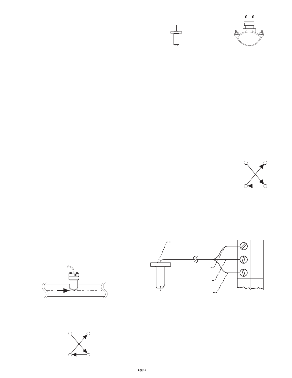
6. Sensor
Wiring
Blk
F-
Red
F+
Shld.
525
black
(AC signal out)
red
(AC signal out)
silver
(ground)
Instruments
1/2 in. NPT
conduit port
Flow
Flow sensor
arrow
Fitting
flange
3. Slip two washers onto each bolt and insert the bolt/washer
onto each of the four fi tting fl ange holes.
4. Snug all four fl ange bolts in a criss-cross pattern. Using a
torque wrench (when possible), torque the fl ange nuts in a
crisscross pattern to 52 foot pounds.
1
4
2
3
Flange
bolt torque
pattern
+GF+
Saddle Fitting,
hardware included
525-3
Sensor
(525-3S for stainless steel pin)
Wetted fitting materials:
Ductile Iron, 347 SS,
Carbon Steel,
Buna-N/Neoprene
Signet Mini-Tap Fittings, 1.25 to 12 inch:
• Drill a 27 mm (1-1/16 in.) diameter hole completely through the
ONE surface of the pipe. Thoroughly deburr inner and outer
edges of hole.
• Tack weld the Mini-Tap fi tting onto the pipe, making sure the
hole in the pipe is lined up with the Mini-Tap fi tting hole.
• Weld the Mini-Tap fi tting onto the pipe.
4.2 Installation, Saddle Fittings
1. Select an appropriate mounting location as outlined in
sections 1 and 2.
2. Drill a 27 mm (1-1/16 in.) diameter hole completely through
the TOP surface of the pipe. Thoroughly deburr inner and
outer edges of hole.
3. Place the Buna-N/Neoprene saddle O-ring over the pipe hole
(small hole side towards pipe). Position the saddle fi tting
over the O-ring, making sure the O-ring
centers on the underside fi tting ridge.
Center saddle fi tting and O-ring over the
pipe hole, then strap the fi tting to the pipe
with the two U-bolts. Snug all four nuts
in a criss-cross pattern. Using a torque
wrench (when possible), torque the
U-bolts in a criss-cross pattern to 52 foot pounds.
• Use 2-conductor shielded cable for cable splices to 60 m
(200 ft).
• Maintain cable shield through splice.
• Shield the unjacketed silver (ground) wire using electrical tape
to prevent potential noise interference and/or shorting hazards.