Flow sensor insertion/removal – GF Signet 3519 Flow Wet-Tap Valve User Manual
Page 3
3
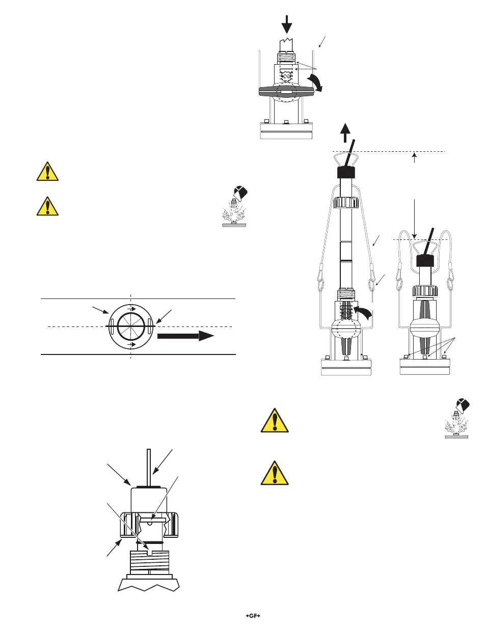
Signet 3519 Flow Wet-Tap Assembly
clamps
safety
cable
Hex
bolts
(6 ea.)
OPEN
SENSOR
STROKE AREA
P3 sensor = 197 mm (7.75 inches)
P4 sensor = 229 mm (9 inches)
P5 sensor = 305 mm (12 inches)
black conduit
cap
PROCESS PIPE
(TOP VIEW)
direction of flow
sensor bale
Figure 3
Figure 2
O-rings
brackets
CLOSED
Figure 1
7. Align the tabs under the sensor cap with the notches on the
fi tting insert and tighten the sensor cap (Figure 4).
• HAND TIGHTEN ONLY. DO NOT use any tools that may
damage plastic parts.
Figure 4
sensor
bale
sensor
cap
tab
black
conduit
cap
notch
3. Flow Sensor Insertion/Removal
To insert the fl ow sensor:
1. Lubricate O-rings with a non-petroleum based, viscous
lubricant (grease) compatible with the system.
2. Carefully insert the sensor into the 3519 valve assembly until
the fi rst two O-rings seat inside the bore (Figure 1).
• Do not damage the rotor on closed ball valve.
3. Using the clamps, attach the sensor safety cable to the
3519 assembly brackets (hand tighten only).
4. Pull
the
fl ow sensor upward to remove slack in the safety
cables (Figure 2).
WARNING: Safety cables are factory installed at precise
length. DO NOT attempt to service or replace safety
cables.
WARNING: System pressure must be 25 psi
or less prior to sensor insertion or removal.
5. Open the ball valve (Figure 2).
6. Using a twisting motion, push the fl ow sensor into the 3519
assembly.
• Turn the sensor so the arrows on the black conduit cap
point in the direction of fl ow.
• When properly aligned, the sensor bale will be parallel with
the pipe (Figure 3).
To remove the fl ow sensor:
WARNING: System pressure must be
25 psi or less prior to fl ow sensor insertion
or removal. Stay clear of sensor stroke
area and safety cable during sensor
removal.
WARNING: Check the six (6) Hex bolts (Figure 2)
prior to unscrewing the sensor cap. If bolts are loose,
tighten securely before proceeding.
1. Unscrew the sensor cap. (DO NOT use any tools that may
damage plastic parts.)
2. Carefully pull the fl ow sensor upward with a twisting motion
until the safety lanyards are fully extended (Figure 2).
3. Close the ball valve (Figure 1).
4. Loosen the relief plug to depressurize the sensor area.
5. Disconnect the sensor safety cable clamps from the 3519
assembly brackets.
7. The sensor can now be safely removed.