Signet fittings, Wet-tap valve installation – GF Signet 3519 Flow Wet-Tap Valve User Manual
Page 2
2
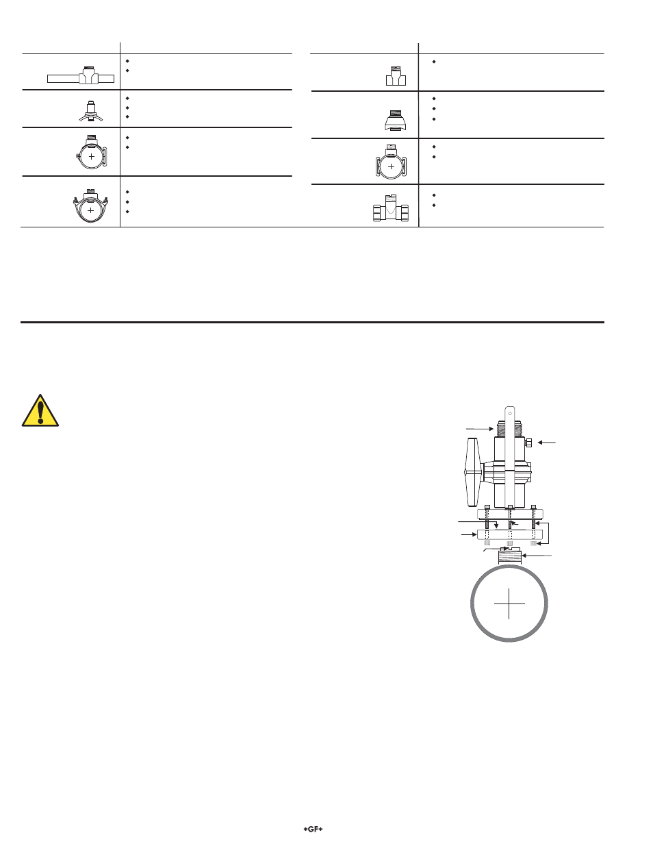
Signet 3519 Flow Wet-Tap Assembly
3. Signet Fittings
Type Description
2 to 4 inch, cut 1-7/16 inch hole in pipe
Over 4 inch, cut 2-1/4 inch hole in pipe
Special order 14 in. to 36 in.
0.5 to 4 inch versions
PVC or CPVC
2 to 4 inch, cut 1-7/16 inch hole in pipe
6 to 8 inch, cut 2-1/4 inch hole in pipe
Available in 10 and 12 inch sizes only
Cut 2-1/2 inch hole in pipe
Weld in place using solvent cement
0.5 to 2 inch versions
Carbon steel &
stainless steel
threaded tees
Carbon steel &
stainless steel
Weld-on
Weldolets
2 to 4 inch, cut 1-7/16 inch hole in pipe
Over 4 inch, cut 2-1/4 inch hole in pipe
See section 4 below for details
For pipes DN 65 to 200 mm
Requires a 30 mm diam. hole in the pipe
For pipes from DN 15 to 50 mm
PP or PVDF
Type Description
Plastic tees
Metric
PVC-U
Saddle
Metric
Union
Fitting
PVC
Clamp-on
Saddles
Iron
Strap-on
saddles
PVC
Glue-on
Saddles
Consult the Signet Measurement and instrumentation Catalog for a complete listing of installation fi ttings.
Valve handle
(shown in
open position)
Pressure
relief plug
Align notch and key
under wet tap flange
parallel with pipe.
Allen bolts
and hex nuts
Support plate
Viton O-ring
Key
Sealant
1-1/4 X 11-1/2 in.
NPSM thread
4. Wet-Tap Valve Installation
The Signet 3519 Flow Wet-Tap Assembly attaches directly to Signet installation fi ttings to enable fl ow sensor removal without system
shutdown. It consists of a fl ange and support plate which thread onto the pipe fi tting insert, and a PVC ball valve through which an
extended length fl ow sensor is inserted into the pipe.
CAUTION: The 3519 Flow Wet-Tap Valve may only be installed into, and
removed from, non-pressurized systems (0 psig).
Procedure
1. Remove six hex nuts and bolts from the Wet-Tap fl ange. Separate the support plate
from the main assembly. Be sure that the Viton O-ring is properly seated in the
support plate groove.
2. Apply sealant to the pipe fi tting insert threads to prevent leaks.To eliminate any
leakage, the valve can be sealed to the fi tting using one of these two methods:
1. Use a silicone RTV such as “GE Sealants and Adhesives Silicone II”.
2. Use a PVC cement such as Christy’s “Red Hot Blue Glue” (for PVC fi ttings) or a
similar PVC pipe cement.
NOTE: This will permanently bond the valve to the installation fi tting and the
fast drying period will not allow for errors in the installation process.
3. Screw support plate onto pipe fi tting insert (O-ring side facing up). It must be
threaded completely down until the notches at the top of the pipe fi tting insert
are exposed.
4. Mount the main Wet-Tap Assembly on the support plate. Make certain the
alignment keys on the fl ange mate with the notches on the pipe fi tting insert.
5. Loosen support plate (holding the main Wet-Tap Assembly in place) until it resists
slightly. Loosen an additional 1/4-turn to seat O-ring.
6. Replace the six hex nuts and bolts to secure the Wet-Tap Assembly in place. Adjust the support plate position as necessary
to align screws.
7. Check the pressure relief plug on Wet-Tap Assembly. It must be closed fi nger tight to prevent leaks.
8. Close ball valve by turning the handle to the fully closed position (parallel with pipe).