Description of system, Configuration and function – Burkert Type 8697 User Manual
Page 8
8
Description of system
5.
DescripTiOn Of sysTem
5.1.
configuration and function
The Pneumatic Control Unit Type 8697 can control single or double-
acting process valves. The Pneumatic Control Unit Type 8697 has been
optimized for integrated, modular installation on process valves of the
21xx series (Element actuator size ∅ 50). The module configuration
permits a variety of expansion steps.
For installation on the 20xx series there is a special model which is
described in Chapter “5.1.2”.
5.1.1. pneumatic control unit for integrated
installation on 21xx series (element
actuator size ∅ 50)
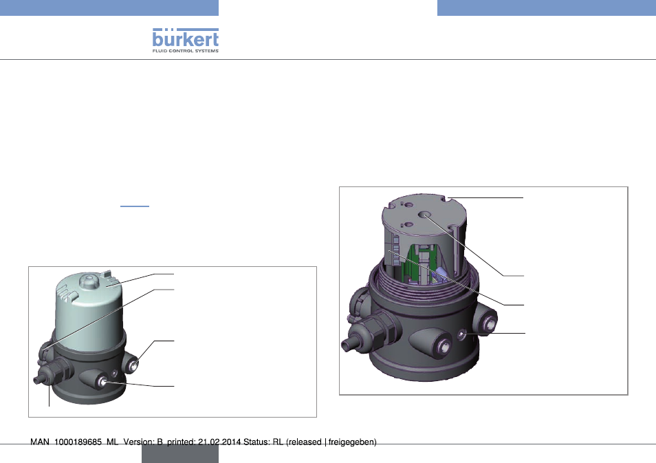
Cable gland M16 x 1.5 or Circular plug-in connector M12 x 1
Exhaust air con-
nection label: 3
Pressure limiting valve
(for protection against too high
internal pressure in case of
error)
Pilot air port
label: 1
Transparent cap
Fig. 1: Configuration and function (1)
Optical position indicator:
The device status is displayed on the Pneumatic Control Unit (yellow
mark).
Option: electrical position feedback
Optionally mechanical limit switches (micro switches) or inductive
proximity switches can measure the valve position.
View without transparent cap:
Fastening screws (2x)
Screw terminals
Assembly shaft for
precision adjustment
of the switch cams
(only for model with
inductive proximity
switches)
Opening for optical
position indicator
Fig. 2: Configuration and function (2)
english
Type 8697