Burkert Type 8697 User Manual
Page 16
16
Installation
Guide element
O-ring
Plastic part of the
switch spindle
Switch cam
Switch spindle
Spindle (actuator)
Actuator cover
Groove ring
3
Spacer sleeve
Maximum
distance
Fig. 10: Installation of the switch spindle (2), series 20xx
→
Tighten the guide element with a wrench SW19 into the actuator
cover (torque: 8.0 Nm).
→
Tighten the switch spindle on the spindle of the actuator. To do
this, there is a slot on the upper side (torque: 1.0 Nm).
→
Push spacer sleeve onto the switch spindle up to the guide element.
Position switch cams on the switch spindle:
→
Push lower switch cam up to the spacer sleeve.
→
Push upper switch cam until 3 mm from the start of the switch
spindle.
Ensure that the distance between both switch cams is maximum
(see “Fig. 10”).
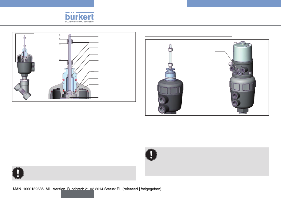
2. installation of the pneumatic control unit
Fastening screws
max. 0.5 Nm
Fig. 11: Installation of the Pneumatic Control Unit, series 20xx
→
Push the Pneumatic Control Unit onto the actuator.
→
Press the Pneumatic Control Unit all the way down as far as the
actuator and turn it into the required position.
Ensure that the pneumatic connections of the Pneumatic
Control Unit and those of the actuator are situated preferably
vertically one above the other (see “Fig. 11”).
If they are positioned differently, longer hoses may be required
other than those supplied in the accessory kit.
english
Type 8697