Installation on process valves of series 21xx – Burkert Type 8697 User Manual
Page 13
13
Installation
7.2.
installation on process valves of
series 21xx
procedure:
1. install switch spindle
Transparent cap
Actuator
Pilot air ports
(plug-in hose con-
nectors with collets or
threaded bushings)
Fig. 5: Installation of the switch spindle (1), 21xx series
→
Unscrew the transparent cap on the actuator and unscrew the
position display (yellow cap) on the spindle extension.
→
For version with plug-in hose connector, remove the collets (white
nozzles) from both pilot air ports (if present).
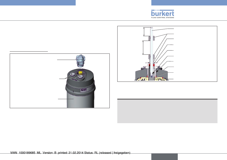
O-ring
Spindle extension
Guide element
Actuator cover
Groove ring
Switch spindle
Switch cam
3
max. 5 Nm
max. 1 Nm
Spacer sleeve
Maximum
distance
Fig. 6: Installation of switch spindle (2), 21xx series
note!
improper installation may damage the groove ring in the
guide element.
The groove ring is already be pre-assembled in the guide element
and must be “locked into position” in the undercut.
▶ When installing the switch spindle, do not damage the groove ring.
→
Push the switch spindle through the guide element.
english
Type 8697