Burkert Type 8697 User Manual
Page 25
25
Electrical installation
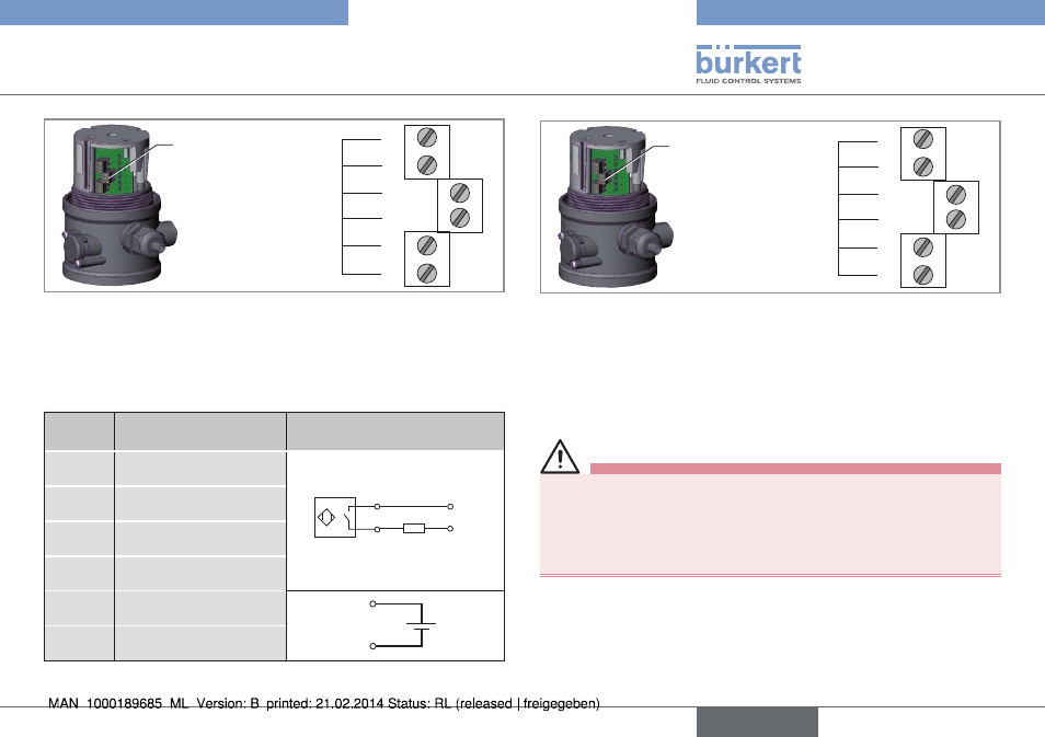
Screw terminals
1
2
3
Terminal No
4
5
6
Fig. 20: Position of the screw terminals
9.2.4. connection diagram with two-wire
proximity switches 24 V (inductive
limit switches, normally open)
terminal configuration
external circuit
1
INI Top +
+
–
load
1 / 3
2 / 4
2
INI Top -
3
INI Bottom +
4
INI Bottom -
5
Valve control +
5
6
6
Valve control GND
Tab. 5: Connection diagram with two-wire proximity switches 24 V
Screw terminals
1
2
3
Terminal No
4
5
6
Fig. 21: Position of the screw terminals
9.3.
electrical installation with
circular plug-in connector
Danger!
risk of electric shock.
▶ Before reaching into the device, switch off the power supply and
secure to prevent reactivation.
▶ Observe applicable accident prevention and safety regulations
for electrical equipment.
→
Connect the pins.
english
Type 8697
- Type 0125 (15 pages)
- Type 0121 (4 pages)
- Type 6012 (4 pages)
- Type 0330 (2 pages)
- Type 0331 (4 pages)
- Type 0127 (18 pages)
- Type 0131 (5 pages)
- Type 0141 (5 pages)
- Type 0142 (12 pages)
- Type 0145 (3 pages)
- Type 0174 (5 pages)
- Type 0212 (2 pages)
- Type 0211 (5 pages)
- Type 0212-B (18 pages)
- Type 0250 (64 pages)
- Type 0253 (2 pages)
- Type 0255 (15 pages)
- Type 0355 (2 pages)
- Type 0255 (2 pages)
- Type 8640 (55 pages)
- Type 8640 (119 pages)
- Type 8006 (34 pages)
- Type 8640 (2 pages)
- Type 0256 (15 pages)
- Type 0256 (2 pages)
- Type 0258 (72 pages)
- Type 0262 (5 pages)
- Type 0273 (6 pages)
- Type 0280 (12 pages)
- Type 0280 (5 pages)
- Type 0280 (2 pages)
- Type 0281 (2 pages)
- Type 0282 (2 pages)
- Type 0283 (2 pages)
- Type 0286 (4 pages)
- Type 0287 (15 pages)
- Type 0290 (14 pages)
- Type 0290 (2 pages)
- Type 0293 (18 pages)
- Type 0300 (6 pages)
- Type 0301 (6 pages)
- Type 0311 (2 pages)
- Type 0312 (6 pages)
- Type 6519 (4 pages)
- Type 6519 (2 pages)