Safety positions, Accessories – Burkert Type 8697 User Manual
Page 28
28
Safety Positions
→
Pressurize pilot air port 1 with compressed air (5 bar) or, if fitted,
actuate the hand lever of the pilot valve in the control unit: Actuator
moves to the 2nd end position.
The switch cams (and switch points) have now been set.
→
Check the switching point(s) using suitable measuring equipment.
→
If required, the switch points can still be finely adjusted: Using a
screwdriver, push switch cams towards the middle (see “Fig. 26”).
→
Check that the seal is correctly positioned in the transparent cap.
(“Fig. 17: Position of the seal in the transparent cap”, page 23).
note!
damage or malfunction due to penetration of dirt and humidity.
To ensure degree of protection IP65 / IP67:
▶ Screw the transparent cap in all the way.
→
Close the Pneumatic Control Unit (assembly tool: 674078
5)
).
Switch cam
Fig. 26: Adjustment of the micro switch and the proximity switches
6)
The assembly tool (674078) is available from your Bürkert sales
office.
10.
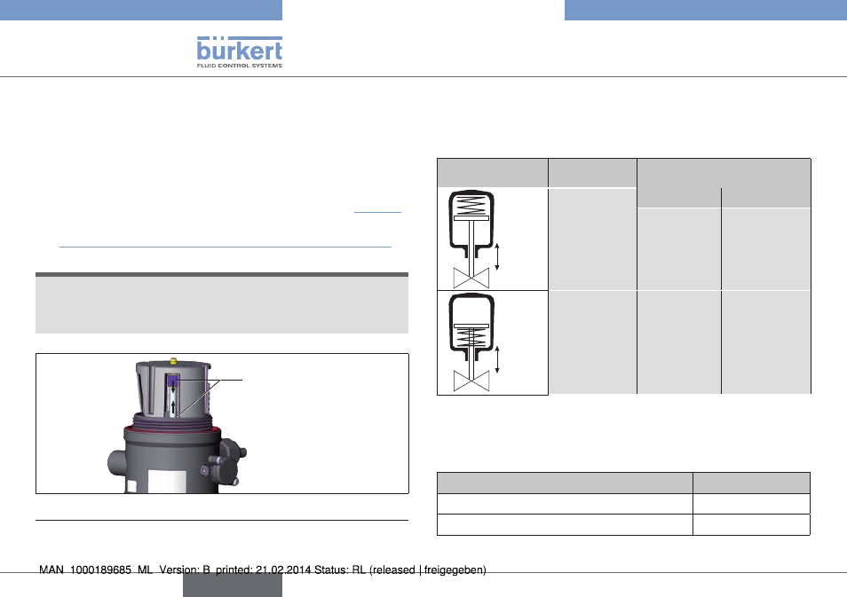
safeTy pOsiTiOns
safety positions after failure of the electric or pneumatic auxiliary
energy:
Operating mode designation
safety positions after failure
of the auxiliary energy
up
down
Single-acting
control
function A
electrical
pneumatic
down
down
up
down
Single-acting
control
function B
up
up
Tab. 7: Safety positions
11.
accessOries
designation
Order no.
Connection cable M12 x 1, 8-pole
919061
Assembly tool
674078
Tab. 8: Accessories
english
Type 8697