Burkert Type 8697 User Manual
Page 23
23
Electrical installation
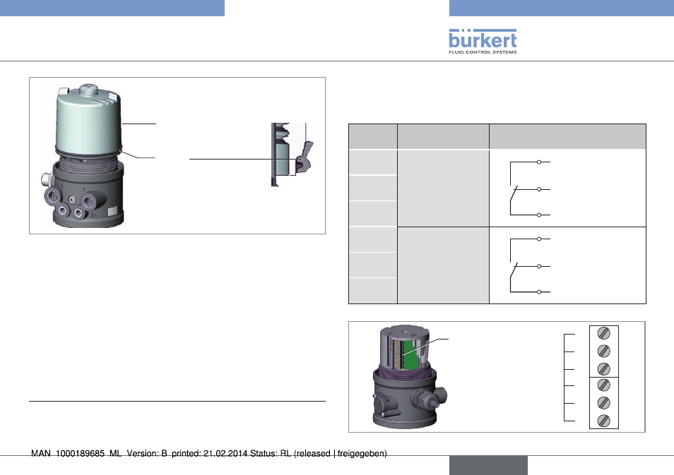
Transparent cap
Joint
Transparent cap
Fig. 17: Position of the seal in the transparent cap
→
Check that the seal is correctly positioned in the transparent cap.
→
Close the Pneumatic Control Unit (assembly tool: 674078
1)
).
1)
The assembly tool (674078) is available from your Bürkert sales
office.
9.2.1. connection diagram
with micro switches
(mechanical limit switches)
terminal configuration
external circuit
1
Micro switch
top
1
2
3
NO
Joint
connection
NC
2
3
4
Micro switch
bottom
4
5
6
NO
Joint
connection
NC
5
6
Tab. 2: Connection diagram with micro switches
Screw terminals
1
2
3
Terminal No
4
5
6
Fig. 18: Position of the screw terminals
english
Type 8697
See also other documents in the category Burkert Accessories for water:
- Type 0125 (15 pages)
- Type 0121 (4 pages)
- Type 0330 (2 pages)
- Type 0331 (4 pages)
- Type 6012 (4 pages)
- Type 0127 (18 pages)
- Type 0131 (5 pages)
- Type 0141 (5 pages)
- Type 0142 (12 pages)
- Type 0145 (3 pages)
- Type 0174 (5 pages)
- Type 0212 (2 pages)
- Type 0211 (5 pages)
- Type 0212-B (18 pages)
- Type 0250 (64 pages)
- Type 0253 (2 pages)
- Type 0255 (15 pages)
- Type 0355 (2 pages)
- Type 0255 (2 pages)
- Type 8006 (34 pages)
- Type 8640 (2 pages)
- Type 8640 (55 pages)
- Type 8640 (119 pages)
- Type 0256 (15 pages)
- Type 0256 (2 pages)
- Type 0258 (72 pages)
- Type 0262 (5 pages)
- Type 0273 (6 pages)
- Type 0280 (5 pages)
- Type 0280 (2 pages)
- Type 0280 (12 pages)
- Type 0281 (2 pages)
- Type 0282 (2 pages)
- Type 0283 (2 pages)
- Type 0286 (4 pages)
- Type 0287 (15 pages)
- Type 0290 (2 pages)
- Type 0290 (14 pages)
- Type 0293 (18 pages)
- Type 0300 (6 pages)
- Type 0301 (6 pages)
- Type 0311 (2 pages)
- Type 0312 (6 pages)
- Type 6519 (4 pages)
- Type 6519 (2 pages)