Burkert Type 2037 User Manual
Page 31
31
Repairs
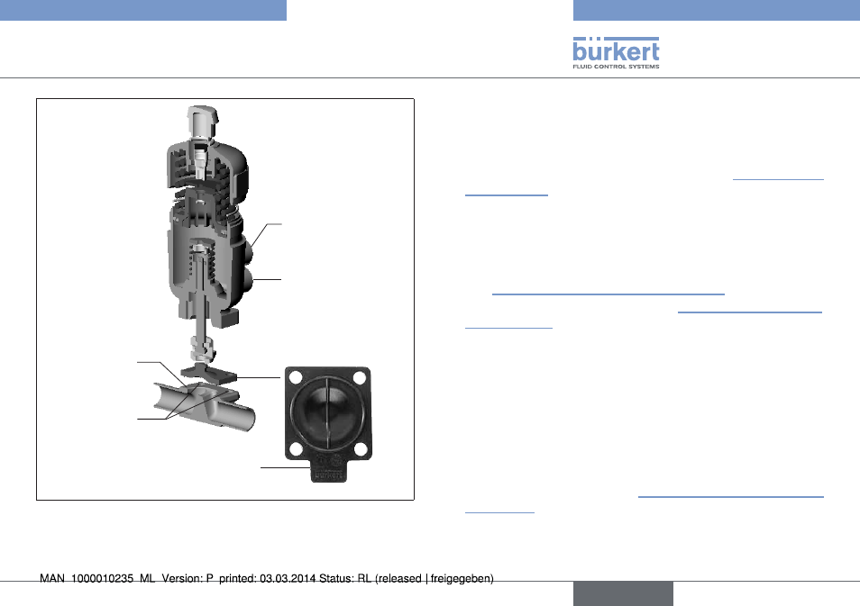
4 fastening
screws
Diaphragm
Body
Lower control air con-
nection
(for CFA and CFI)
Upper control air con-
nection
(for CFB and CFI)
Mark tab for direction
of flow
example
Fig. 31: Replacement of diaphragm
replacement of the diaphragm for control function a
→
Clamp the valve body in a holding device (applies only to valves
not yet installed).
→
Pressurize lower control air connection with compressed air (value
as indicated on the type label) (see picture below “Fig. 32: Control
air connection”). This is required to detach the diaphragm without
damage from the body.
→
Loosen fastening screws crosswise and remove actuator together
with diaphragm from the body.
→
Unbutton or unscrew the old diaphragm. If attachment is with a
bayonet catch, remove the diaphragm by rotating it through 90°
(see “Tab. 10: Fastening types for diaphragms”).
→
Install new diaphragm in actuator (see “Tab. 10: Fastening types
for diaphragms”).
→
Align diaphragm.
Observe mark tab for direction of flow!
→
Place actuator back on the body.
→
Lightly cross-tighten the body screws until the diaphragm is
between the body and actuator.
do not tighten the screws yet.
→
Actuate the diaphragm valve twice to position the diaphragm
correctly.
→
Without applying pressure, tighten the body screws to the per-
mitted tightening torque (see “Tab. 11: Tightening torques for
diaphragms”).
→
Pressurize lower control air connection with compressed air (value
as indicated on the type label).
→
Check the tightening torque of the screws again.
english
Type 2030, 2031, 2031 K, 2032,
2033, 2037