Tab. 9: tight, Ening torques for diaphragms”), Fig. 29: control air – Burkert Type 2037 User Manual
Page 26: Connection”)
26
Installation
procedure for control function a
→
Pressurize lower control air connection with compressed air
(value as indicated on the type label) (see
→
Place actuator on the body.
→
Lightly cross-tighten the body screws until the diaphragm is
between the body and actuator.
do not tighten the screws yet.
→
Actuate the diaphragm valve twice to position the diaphragm
correctly.
→
Without applying pressure, tighten the body screws to the per-
mitted tightening torque (see “Tab. 9: Tightening torques for
diaphragms”).
→
Pressurize lower control air connection with compressed air (value
as indicated on the type label).
→
Check the tightening torque of the screws again.
procedure for actuator with control functions B and i:
→
Place actuator on the body.
→
Lightly cross-tighten the body screws without pressurization until
the diaphragm is between the body and actuator.
do not tighten the screws yet.
→
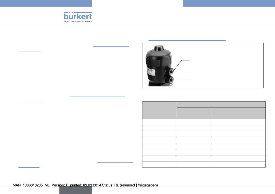
Pressurize upper control air connection with compressed air (value
as indicated on the type label) (see below “Fig. 29: Control air
connection”).
→
Actuate the diaphragm valve twice.
→
Tighten the body screws to the permitted tightening torque (see
“Tab. 9: Tightening torques for diaphragms”).
Lower control air connection
(for CFA and CFI)
Upper control air connection
(for CFB and CFI)
Fig. 29: Control air connection
Orifice
(Diaphragm size)
[mm]
tightening torques for diaphragms [nm]
epdm / fkm
ptfe / advanced ptfe /
laminated advanced ptfe
8
2
2.5
15
3.5
4
20
4
4.5
25
5
6
32
6
8
40
8
10
50
12
15
65
20
30
Tab. 9: Tightening torques for diaphragms
english
Type 2030, 2031, 2031 K, 2032,
2033, 2037